Error
текст ошибки


Sespel automated parking — 96-space preliminary design
Modular linear parking for residential developments: 96 spaces, three independent lifts, six storage levels and separate ground-level bays. The evaluated arrangement has a 485.82 m² operational footprint. The system is in engineering development; figures are preliminary, not certified specifications.
About the product
- StatusPreliminary design — further engineering required
- Capacity96 parking spaces
- Modules3 independent: 36 + 36 + 24
- Lifts and carriages3 lifts / 3 carriages
- Storage levels6 levels
- Ground-level bays3 entry + 3 exit
- Design vehicle massup to 3,000 kg; entry checks required
- Vehicle dimensionsup to 5,300 × 2,300 × 2,200 mm
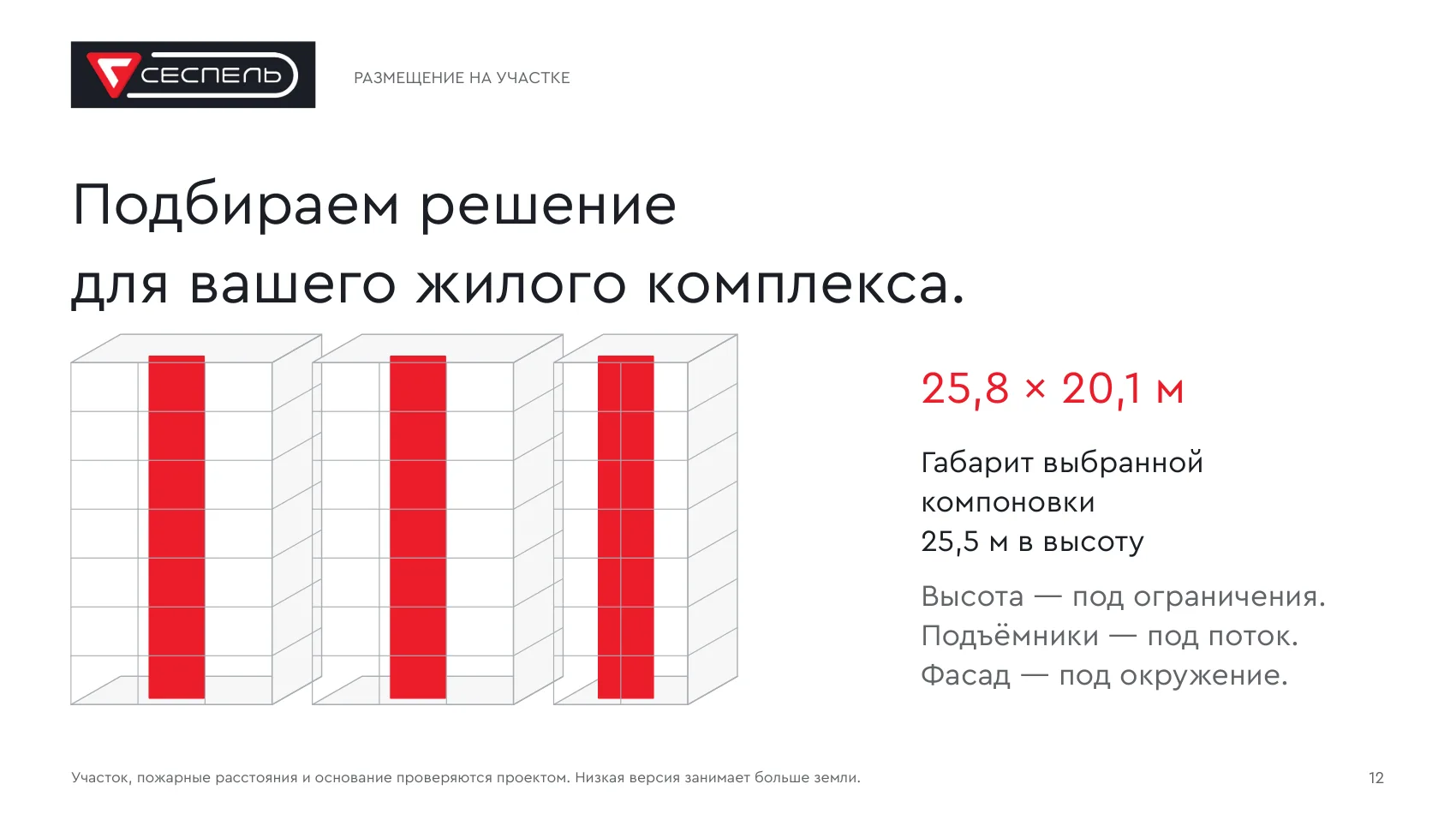
- Layout envelope25.80 × 20.10 × 25.54 m
- Operational footprint485.82 m² (design estimate)
Contact us for more information about this product.
 Sespel automated parking system
Error
Description
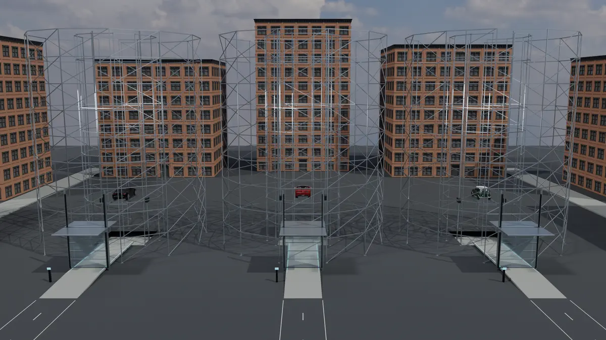
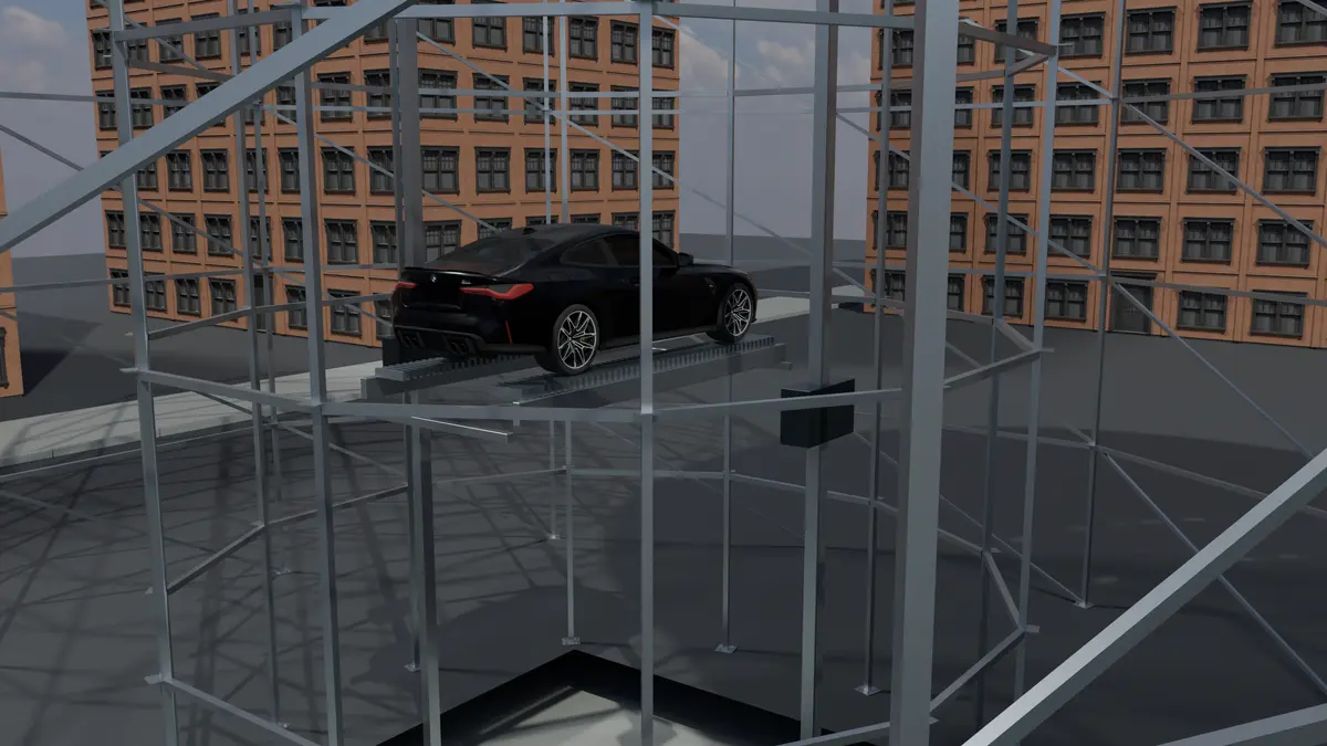
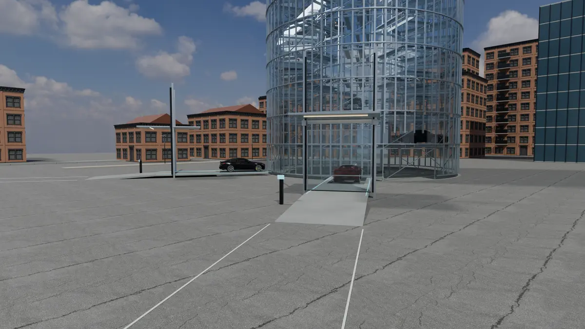
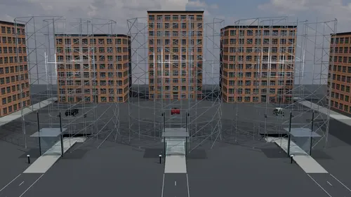
Important: the Sespel parking system shown here is an engineering proposal, not a completed facility or a series-produced product. The top gallery contains computer-generated views of circular towers and individual mechanisms. The 96-space layout selected for further development is linear; its diagrams and design estimates are provided below. The complete vehicle-transfer path and support stiffness require redesign and verification before manufacturing.
Sespel automated parking is intended as a multi-level vehicle storage solution for residential developments. The driver leaves the vehicle in a ground-level arrival bay. Once its parameters are checked, the planned automation moves it to a storage level. A separate ground-level bay is provided for retrieval, without drivers travelling up ramps or through parking floors.
Benefits of the proposed layout
- 96 spaces in three independent linear modules: 36 + 36 + 24; each has its own lift and transfer carriage.
- Separate ground-level entry and retrieval bays reduce interference between vehicle and pedestrian flows.
- Six storage levels reduce the operating footprint by 15.50–15.74% compared with the specific concrete ramp parking alternative assessed.
- When a 36-space module is serviced, the remaining 60 spaces may continue operating if shared infrastructure is functional.
- Repeatable steel sections and straight transfer paths have been selected as a basis for further engineering and manufacturing development.
Core specifications of the 96-space proposal
- Development statusPreliminary layout; not ready for manufacture
- Capacity96 parking spaces
- Independent modules3 modules: 36 + 36 + 24 spaces
- Storage levels6 levels
- Lift mechanisms3 lifts, 3 transfer carriages
- Ground-level bays3 arrival bays and 3 retrieval bays
- Maximum design vehicle mass3,000 kg, subject to entry checks
- Design vehicle envelope5,300 × 2,300 × 2,200 mm including mirrors and roof accessories
- Selected layout height25.54 m
- Operational footprint485.82 m²
- Bounding rectangle25.80 × 20.10 m (518.58 m²)
- Preliminary plot including access and queuingapproximately 1,338 m² in the design model
The figures refer to one preliminary option evaluated on 8–9 October 2026. They are not universal certified specifications and must be refined after site investigation, detailed engineering and project approvals.
Three-module arrangement and operation
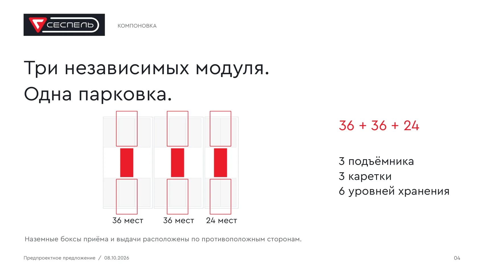
The layout comprises two storage rows across six levels. Each of the three modules has its own lift: two modules hold 36 vehicles each and the third holds 24. Arrival and retrieval bays are positioned on opposite sides at ground level. This arrangement limits shared transport mechanisms and allows modules to be serviced independently.
Linear 36 + 36 + 24 arrangement with three lifts and six levels (preliminary presentation, p. 4)
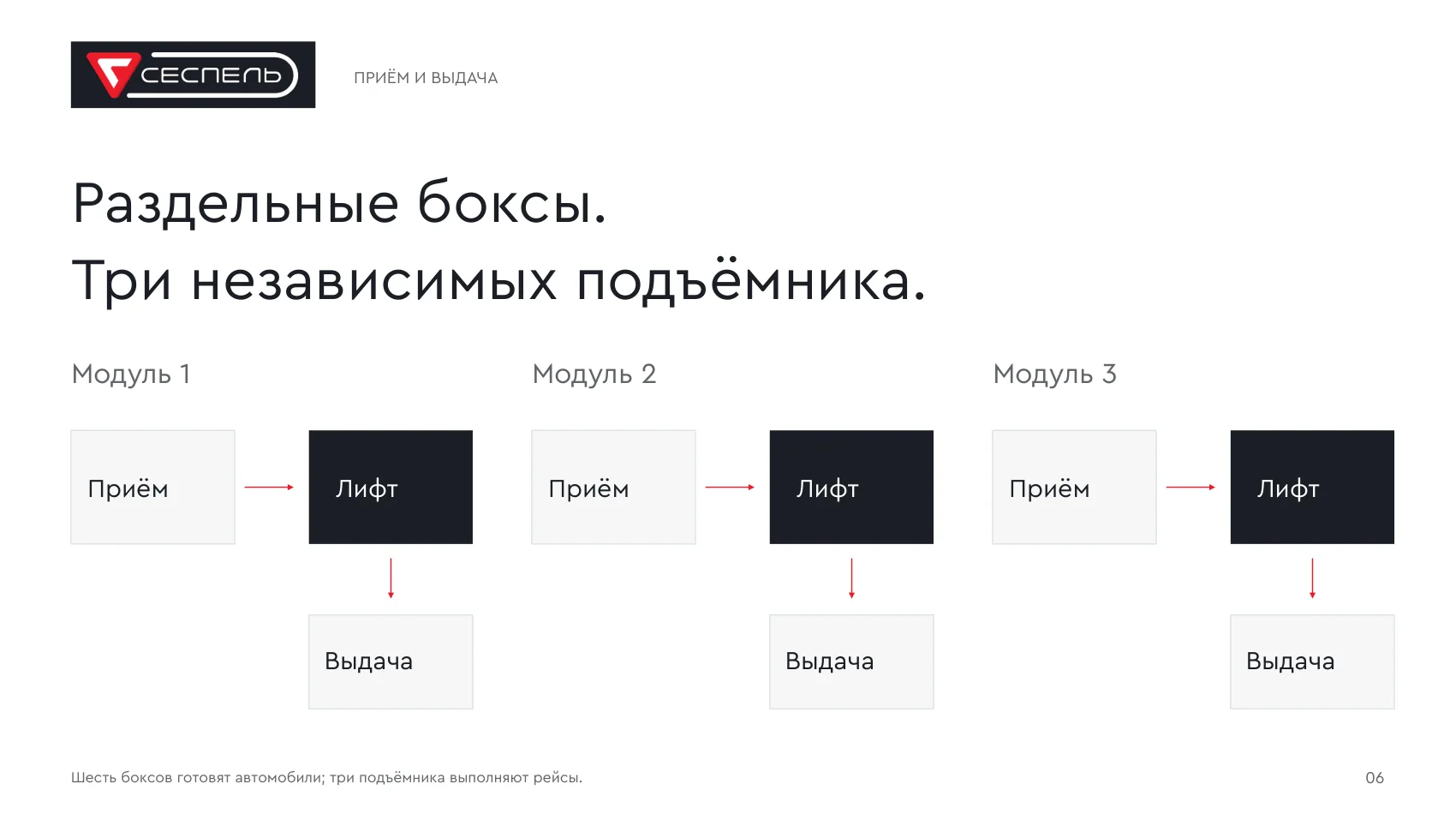
Separate arrival and retrieval bays for each module (presentation, p. 6)

How 60 spaces may remain available when a 36-space module stops (presentation, p. 8)
Proposed 25.8 × 20.1 m arrangement and 25.5 m height (presentation, p. 12)
How drivers drop off and retrieve vehicles
- 1. Arrival: the driver positions the vehicle in a ground-level bay, switches off the engine, closes the doors and exits with passengers.
- 2. Checks: the system is intended to measure envelope, actual mass, wheel loads and axle positioning; admission is rejected if limits are exceeded.
- 3. Storage: after acceptance, the lift and transfer carriage are intended to bring the vehicle to an assigned space.
- 4. Retrieval: on request, the system delivers the car to a separate ground-level retrieval bay; timing depends on the queue and user actions.
The transfer concept uses stationary shelf teeth and a movable comb on the carriage: relative movement transfers support under the wheels between carriage and shelf. This illustrates the principle only. Wheel contact geometry, safe bay flooring, drive assemblies and a continuous transfer path have not yet completed engineering verification.

Driver journey: drop off, confirm acceptance and retrieve from a separate bay (presentation, p. 2)
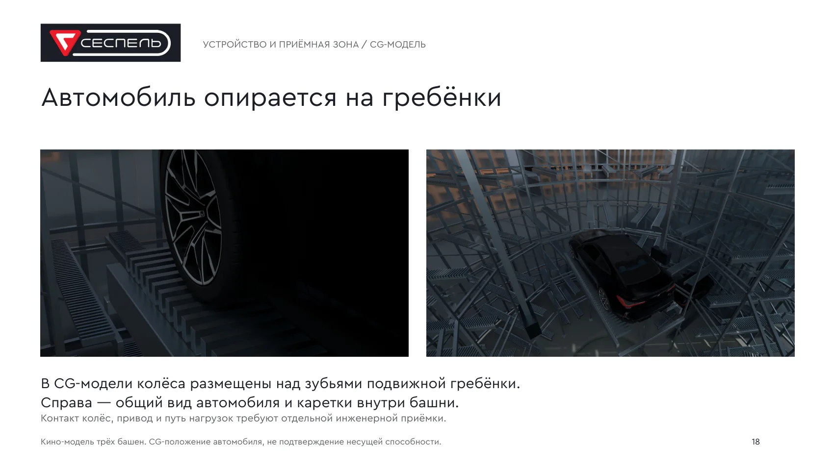
Comb transfer concept — computer-generated images, not a validated mechanism (presentation, p. 18)
Vehicle acceptance criteria
- Length / width / heightno more than 5,300 / 2,300 / 2,200 mm
- Measured actual massup to 2,975 kg with up to 20 kg error and 5 kg reserve
- Maximum design mass3,000 kg; occupants must exit
- Maximum load per wheel1,050 kg including a 5 kg error allowance
- Maximum load on one side1,800 kg including a 10 kg error allowance
- Tyre widthup to 300 mm
- Track width for 300 mm tyres1,500–1,700 mm; assessed on both axles
- Wheelbase2,300–3,300 mm provided both axles are correctly positioned
- Vehicle gross vehicle weight ratingno more than 3,500 kg, with actual mass no more than 3,000 kg
- Further checksmirrors, roof, cargo, centering, wheel positions, closed doors
These are preliminary design-model acceptance criteria, not approved operating instructions. A car meeting the overall size and mass limits is not necessarily eligible: axle position, tyre width and the load on each wheel also matter. The arrival bay requires interlocks that prevent machinery operation while people are present.

Vehicle envelope and mass limits for the evaluated layout (presentation, p. 5)
Retrieval time and throughput simulation
The technical report compares layouts using repeated mixed-demand simulations. At 30 operations per hour, the mean of simulated 95th-percentile readiness times is 6.67 minutes with three lifts versus 10.55 minutes with two. At 50 operations per hour, the three-lift design has a simulated mean P95 of 10.53 minutes. These are model results, not guaranteed retrieval times or certified throughput.
- Simulated demand30 operations/hour, mixed demand
- Three lifts — average readiness P956.67 min in simulation
- Two lifts — average readiness P9510.55 min in simulation
- Three lifts at 50 operations/hour10.53 min, simulated mean P95
- Mean mechanical transfer time126.32 s in simulation
- Modelled driver actions90 s arrival preparation and 60 s collection, modelled separately

Simulated comparison of two and three lifts; actual retrieval time is not guaranteed (presentation, p. 7)
Site planning and comparison with ramp parking
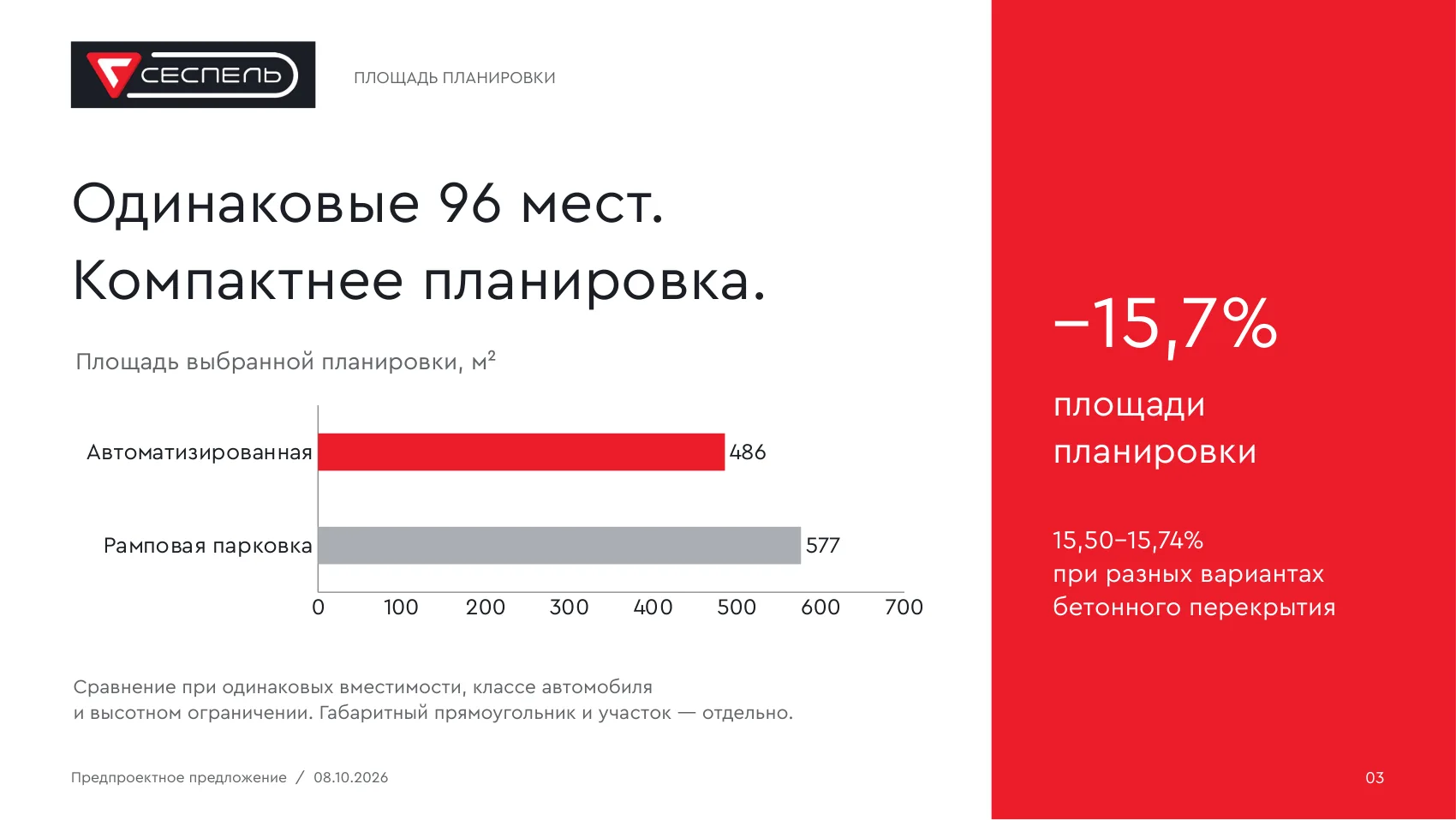
For the same 96 spaces and vehicle class, the selected mechanical arrangement has a 485.82 m² operational footprint. The comparison concrete ramp option uses 574.91–576.58 m², a calculated reduction of 15.50–15.74% under the study assumptions. The automated building bounding rectangle occupies 518.58 m², while the example plot including access lanes is about 1,338 m². These are different measures, and the percentages do not apply to every site.
- Mechanical scheme operational footprint485.82 m²
- Ramp parking operational footprint574.91–576.58 m²
- Reduction in operational footprint15.50–15.74% under the defined assumptions
- Building bounding rectangle518.58 m²
- Example plot including vehicle access1,338 m² for the selected design
- Reduction in total plot area6.69–6.84% compared with the selected concrete alternative
Footprint comparison for 96 spaces — valid only for the evaluated designs (presentation, p. 3)
Structural concept, fabrication and installation
The baseline structural concept uses a steel frame with repeatable profiles and factory-fabricated sections. The proposed process includes plate cutting, edge preparation, welding, straightening, inspection, machining, coating and assembly on site. The engineering proposal envisages manufacturing major metal components at Sespel, while drives, brakes, bearings and safety devices would be specified and sourced to meet technical requirements.
- A multi-storey load-bearing frame and structural beams must carry loads from vehicles and transport mechanisms.
- Stationary shelves and a movable transfer carriage are intended to exchange loads beneath vehicle wheels.
- Three lifts are arranged as independent modules, while shared external services and access areas require separate engineering.
- On-site assembly is planned from factory sections after checking components, welds and site connections.

Proposed manufacturing and installation: factory sections, assembly and commissioning (presentation, p. 11)
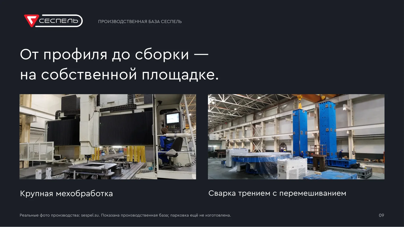
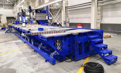
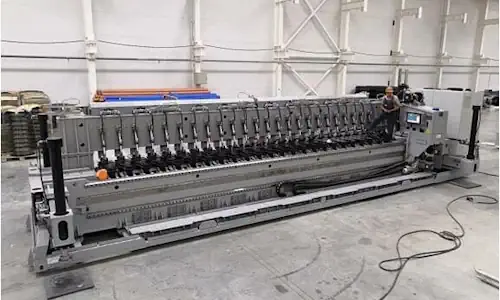
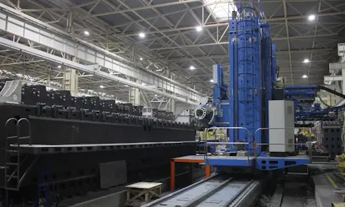
Photos of Sespel manufacturing facilities, not photos of the parking system (presentation, p. 9)
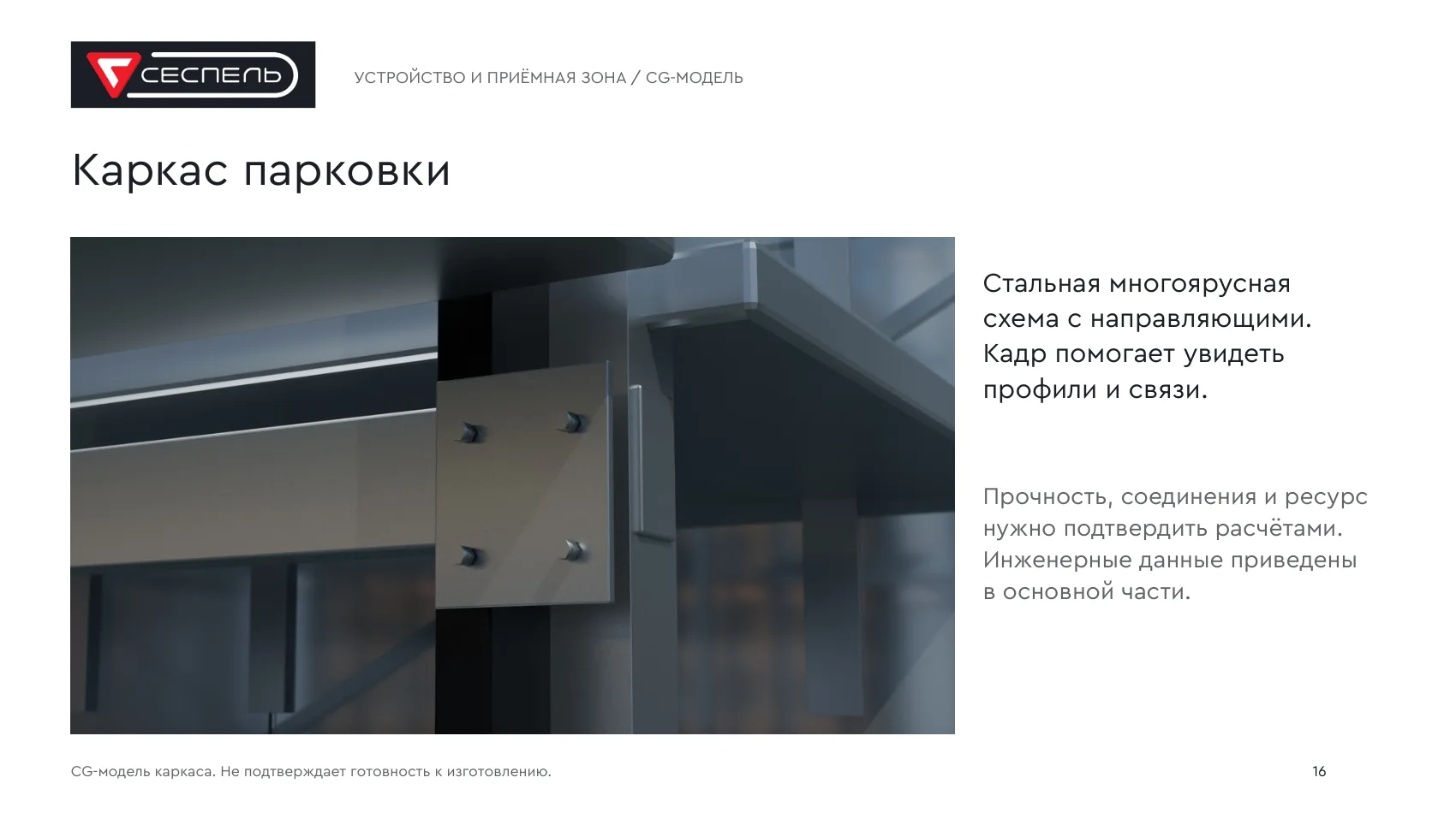
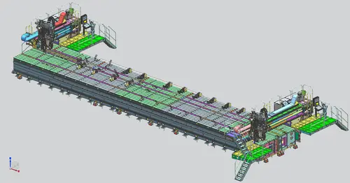
Computer-generated steel frame detail, not a production drawing (presentation, p. 16)
Engineering limitations, safety and development status
The engineering report dated 9 October 2026 identifies two essential issues: shelf-support flexibility exceeds the design limit, and a continuous path for the transfer carriage across supports has not been verified. The layout has therefore been selected for further development but is not ready for manufacturing, installation or use. Frame stability, full-cycle mechanism durability, safety interlocks and regulatory compliance also require verification.
- The site-specific project must address fire separation distances, structural fire classification, enclosures and fire-rated separation of blocks.
- Automatic water-based firefighting or sprinkler measures for each level, evacuation and maintenance access require separate design.
- EV and plug-in hybrid charging equipment is not included in the proposed configuration.
- Before the system can be released for manufacture, supports must be redesigned, transfer geometry verified, prototype assemblies tested and project approvals obtained.
What we need to develop a site-specific proposal
To prepare a site-specific proposal we need a site plan with approaches and constraints, the target capacity, height limits, vehicle class and size, expected arrival and retrieval demand, ground and utility information, and facade requirements. These inputs allow initial evaluation of feasibility, the number of independent mechanisms and the scope of subsequent engineering. The figures on this page do not replace detailed design or a commercial quotation.
Source documents: “Automated Parking”, Sespel preliminary presentation dated 8 October 2026; “96-Space Parking”, technical summary dated 9 October 2026; and “96-Space Automated Parking: Structural and Manufacturing Design Selection”, technical report dated 9 October 2026. Linear-layout diagrams and technical comparisons are excerpts from the preliminary presentation.
Credits for the existing 3D visualisations: parking geometry by Sespel; Ferrari 458 Italia by vicent091036, BMW M4 CS by eldaaar and Mini Cooper S by kowalski_30 (CC BY 4.0); Poly Haven environment by James Ray Cock, Greg Zaal and Jarod Guest (CC0). Full credits and links: /images/production/parking/automated-parking/credits.txt.
Frequently asked questions
Answers about capacity, vehicle acceptance, module arrangement, simulated retrieval time and development status.
Has Sespel already built the automated parking system?
No. It is a preliminary engineering proposal. The selected 96-space linear scheme still requires redesigned shelf supports and validation of the full vehicle-transfer path. Series-production readiness is not claimed.
Why does the image gallery show circular towers while the specifications describe a linear layout?
Circular towers and entry areas are computer-generated illustrations of the operating concept. The specification figures refer to a separate 36 + 36 + 24 linear arrangement shown in the technical diagrams below.
How many parking spaces and lifts are planned?
The chosen layout has 96 spaces in three modules with 36, 36 and 24 spaces. Each module has a separate lift, transfer carriage, ground-level arrival bay and retrieval bay.
Which vehicles can be accepted?
The design class covers up to 3,000 kg actual mass and 5,300 × 2,300 × 2,200 mm including mirrors and roof items. Tyres, tracks, wheelbase, weight distribution and positioning must also be checked; envelope dimensions alone are insufficient.
Must the driver find a space or drive up a ramp?
In the proposed workflow, the driver leaves the car at ground level, confirms acceptance and exits the bay. Automated mechanisms are intended to store it on a shelf and return it to a separate retrieval bay on request.
How long will retrieval take?
At a simulated demand of 30 operations per hour with three lifts, the average P95 vehicle readiness time is 6.67 minutes. This is not a guarantee: demand, queues and request patterns change the result.
How much more compact is it than ramp parking?
In the study comparison, the operational footprint is 485.82 m² versus 574.91–576.58 m², a 15.50–15.74% reduction under equal 96-space capacity and the stated assumptions. Savings in overall site area are evaluated separately and are not guaranteed for every development.
What happens if a lift is taken out of service?
If a 36-space module stops, the other 60 spaces may remain available provided shared systems are operational. Vehicles in the stopped module are not automatically moved into other modules.
Does the proposal include EV charging?
No. EV and plug-in hybrid charging is not included in the described configuration. Storage rules, fire protection and restrictions for those vehicles require a separate project.
How much floor area and height are needed?
The proposed building envelope is 25.80 × 20.10 m and the height is 25.54 m. The operational footprint is 485.82 m², but the total plot must also include access and queuing; approximately 1,338 m² was used in the model.
Which components are expected to be manufactured by Sespel?
The proposal envisages in-house production of main structural profiles, beams, shelves and repeatable sections for on-site assembly. Drives, brakes, bearings and safety devices would be sourced externally. The manufacturing process remains subject to validation.
What information is needed for a residential-project proposal?
Provide the site plan and access roads, required capacity, height limits, vehicle classes and dimensions, expected traffic, utility and geotechnical information, and facade requirements. This supports comparison of alternatives and definition of detailed engineering needs.