Error
текст ошибки


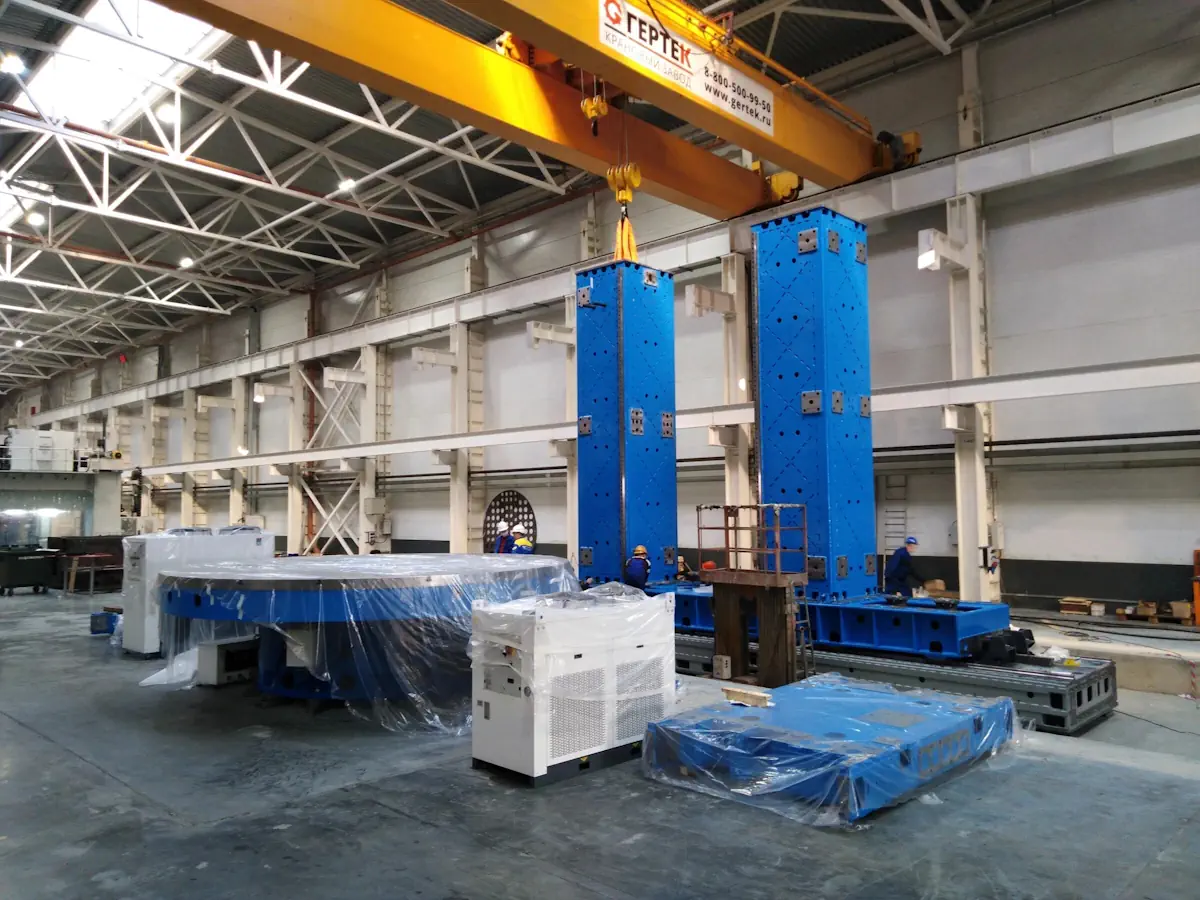
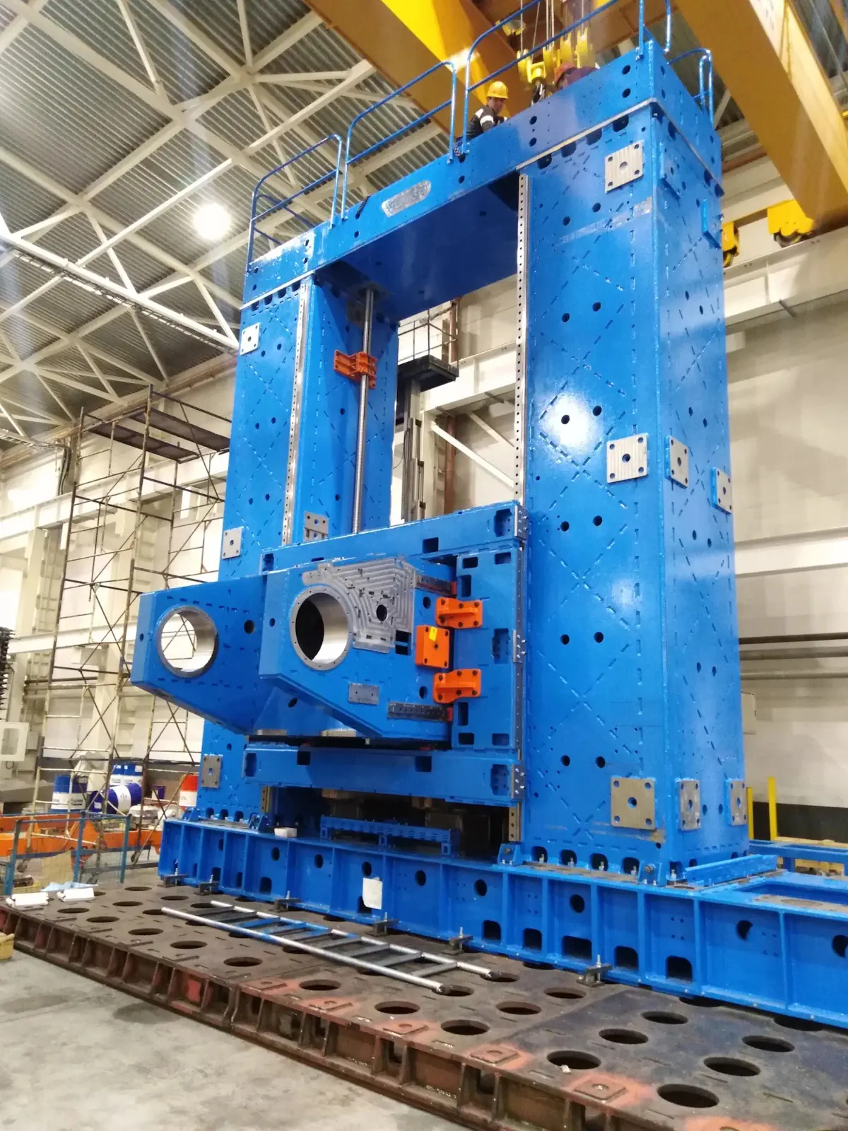
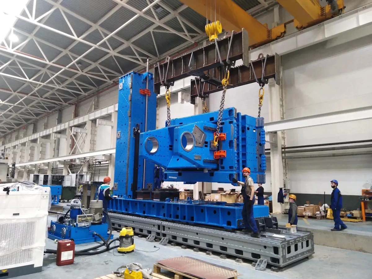
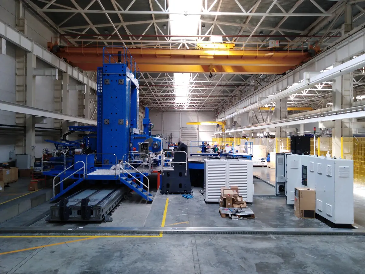
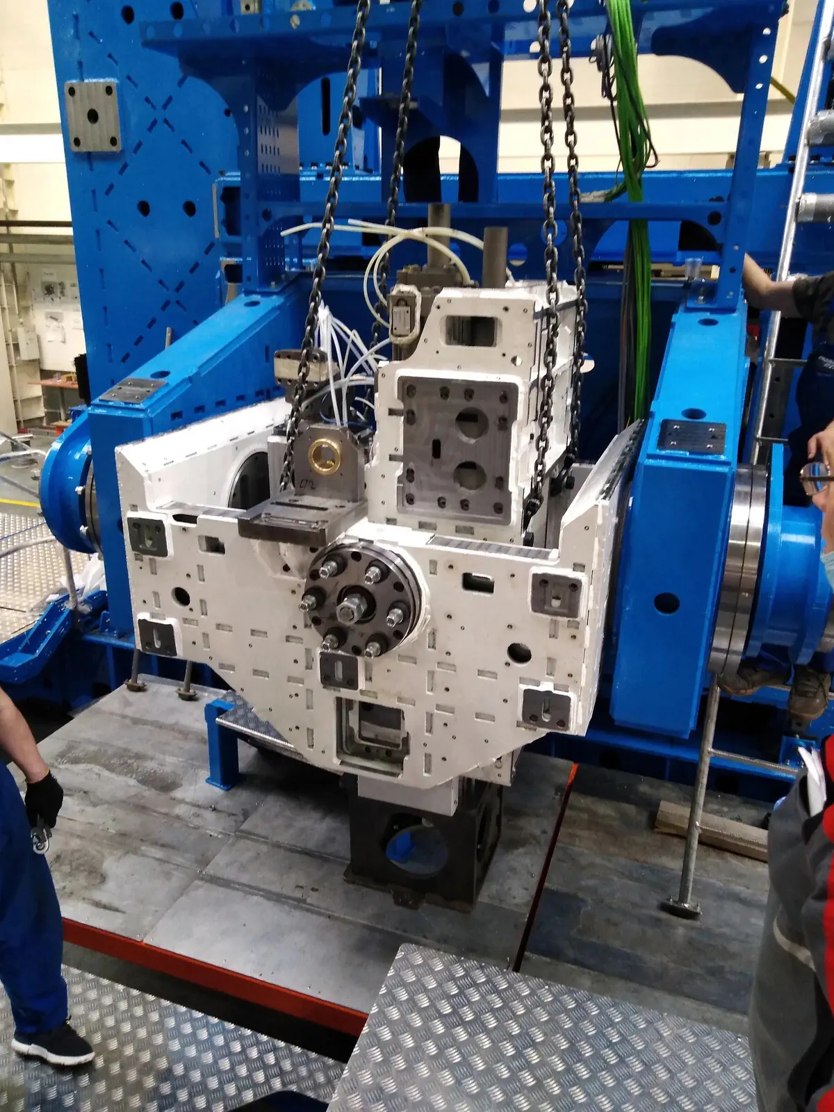
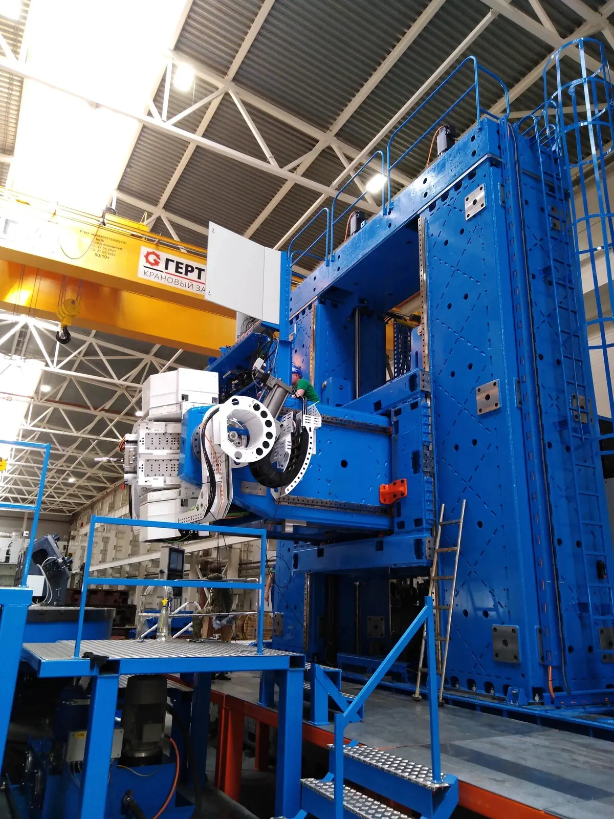
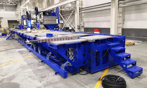
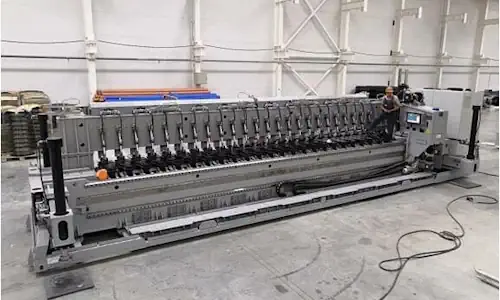
Friction stir welding equipment for tank structures
CNC machine with a 5,000 mm rotary table for friction stir welding aluminium tank structures 3–25 mm thick. 125 kW spindle, X/Y/Z/A/B/U axes, machining and part measurement.
About the product
- ApplicationFSW of aluminium tank structures
- Welded workpiece thickness3–25 mm
- Workpiece outside diameterUp to 5,000 mm
- Workpiece heightUp to 2,000 mm
- Rotary table diameter5,000 mm
- CNC axesX, Y, Z, A, B, U; additional V and W
- Welding spindle power125 kW
- Welding spindle speed0–800 rpm
- Overall dimensions (L × W × H)20,000 × 7,800 × 9,100 mm
- ManufacturerSespel
Contact us for more information about this product.
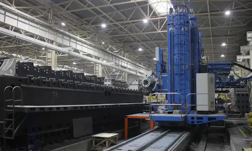 Sespel FSW system for tank structures
Error
Description
STP Sespel (KS0006-00.0000) is an automated friction stir welding (FSW) installation for aluminium products, including tank and cylindrical structures. The system comprises a CNC machine, a rotary table and a mounting plate. It also supports milling, drilling and boring of steel and non-ferrous metal parts.
Welding is performed by a multi-axis electromechanical head with controlled tool tilt, hydraulic spindle feed and independent probe (pin) movement. The rotary table adjusts the position of the clamped workpiece relative to the tool. The capabilities and figures below are taken from operating manual KS0006-00.0000RE (2022).
Applications and workpiece capacity
- Welding processFriction stir welding (FSW)
- Welding materialAluminium and aluminium alloys
- Machining operationsMilling, drilling and boring of steel and non-ferrous metals
- Workpiece outside diameterUp to 5,000 mm
- Workpiece thickness3–25 mm
- Workpiece heightUp to 2,000 mm
- WorkholdingRotary table and mounting plate; workpiece-specific fixtures
The 3–25 mm thickness and dimensions are manual-specified workpiece limits, not a guarantee that every alloy, thickness, joint geometry and tool combination can be welded. The manual does not claim FSW of steel: steel is listed for machining operations.
Machine footprint and main specifications
- Overall dimensions (L × W × H)20,000 × 7,800 × 9,100 mm
- Gross mass160,000 kg
- Rated machine power in the manual1,100 kW
- Accuracy classN — normal accuracy
- Power supply380 V, 50 Hz
- X-axis travel15,850 mm
- Rotary table: work surface diameter5,000 mm
Overall dimensions and power refer to the configuration described in the manual. Workshop planning must also account for foundations, travel clearances, the rotary table, large-workpiece handling and service access.
Machine axes and positioning
The controlled axes are X, Y, Z, A, B and U. Linear axes move the supporting structure and welding head, A and B tilt the tool, and U rotates the workpiece table. The welding head also has hydraulic axial movements V and W for spindle feed and pin extension, respectively.
- X axis — travel / feed15,850 mm / up to 0.005 m/s
- Y axis — travel / feed2,790 mm / up to 0.005 m/s
- Z axis — travel / feed1,420 mm / up to 0.005 m/s
- A axis — tool tilt±45°
- B axis — tool tilt±20°
- V axis — spindle carriage travel80 mm
- W axis — pin travel30 mm
- Rapid traverse X / Y / ZUp to 0.03 / 0.02 / 0.02 m/s
The A and B head angles are set under program control and held by electromagnetic brakes during welding. Linear and rotary encoders provide position feedback. The additional hydraulic V and W movements should not be confused with the six primary machine axes.
Rotary table for tank structures
- Working surface diameter5,000 mm
- Table length including hydrostatic unit5,040 mm
- Table width / height5,800 / 1,570 mm
- Working and rapid rotational speed0–1 rpm
The workpiece fixture is mounted on either the rotary table or the mounting plate. Workpiece rotation helps expose the intended weld area to the head and reduces repeated setups. Fixture design, attachment and accessibility depend on the tank geometry.
Electromechanical welding head and FSW tools
The two-axis electromechanical head comprises rotating housings, drive mechanisms, a spindle and carriage. Welding tools are mounted through a holder with a metric taper shank. Depending on the operation, a fixed or adjustable pin or a Bobbin Tool configuration may be used. Tool changes are manual in the described machine.
- Welding spindle speed0–800 rpm
- Welding spindle motor power125 kW
- Spindle carriage (V)Hydraulic feed, 80 mm
- Welding pin (W)Hydraulic feed, 30 mm
- Head tilt rangesA: ±45°, B: ±20°
The spindle has liquid cooling and oil-air bearing lubrication. Rotary encoder feedback is used to control and monitor spindle speed. The adjustable pin is moved by a separate actuator; it does not imply that every tool can be used without process-specific setup.
Milling, drilling and repair-related operations
In addition to welding, the machine is designed for machining. The manual describes a milling head and a high-speed TEKNOMOTOR electrospindle for aluminium alloy processing. An industrial vacuum system collects chips. It also describes special tooling for plugging a prepared hole or crater under a dedicated repair process.
- Milling electrospindleTEKNOMOTOR, 6 kW
- Milling electrospindle speed6,000–12,000 rpm
- Tool changeManual; a tool storage rack is provided
- Chip removalIndustrial vacuum extraction during milling
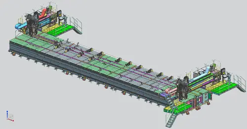
Machine construction in technical illustrations
These manual illustrations show the machine layout, welding head, tool variants and motion assemblies. Open an illustration for a closer look; original equipment photos remain in the main gallery.
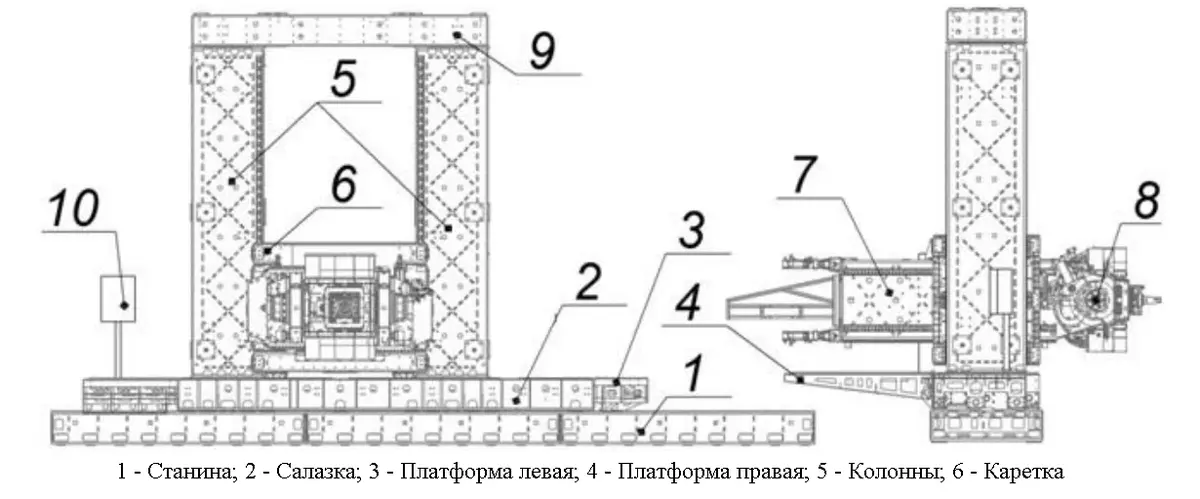
CNC machine layout: bed, columns, carriage and welding head (manual, fig. 1)
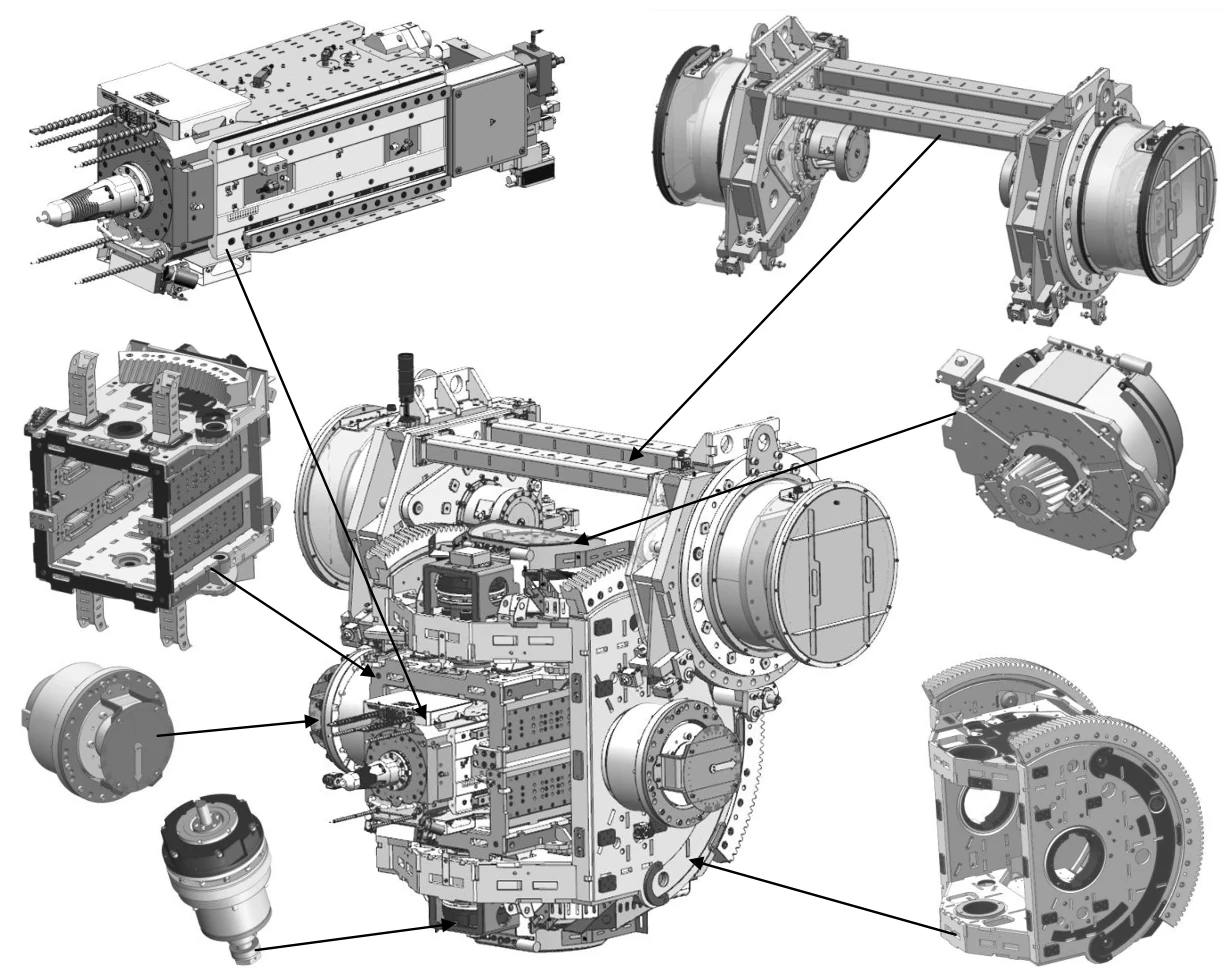
Electromechanical welding head and main assemblies (manual, fig. 3)
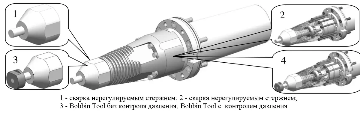
FSW tools with fixed or adjustable pins and Bobbin Tool variants (manual, fig. 4)
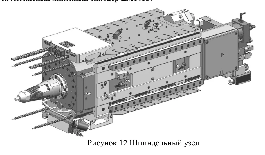
Spindle assembly for friction stir welding (manual, fig. 12)
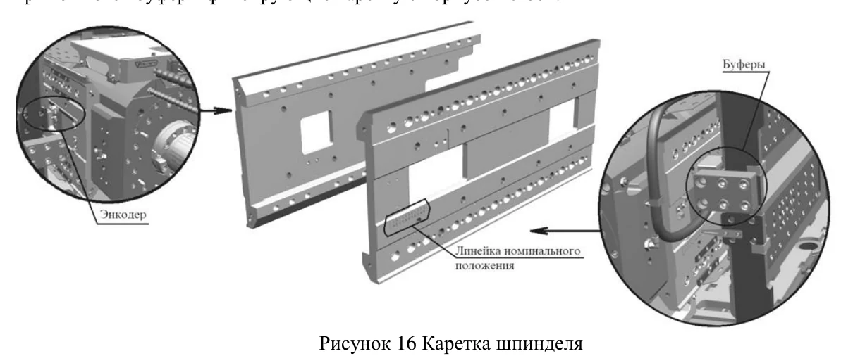
Welding spindle carriage and linear feed components (manual, fig. 16)
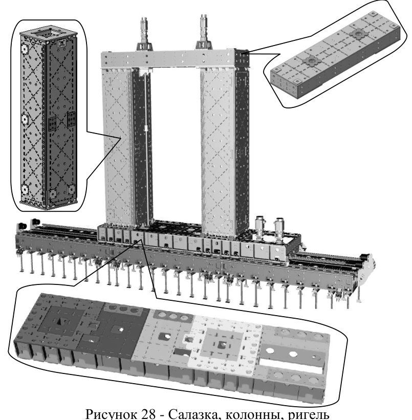
Saddle, columns and crossbeam of the load-bearing structure (manual, fig. 28)
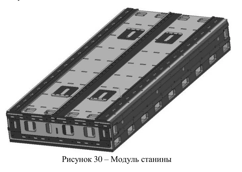
Rigid machine-bed module (manual, fig. 30)
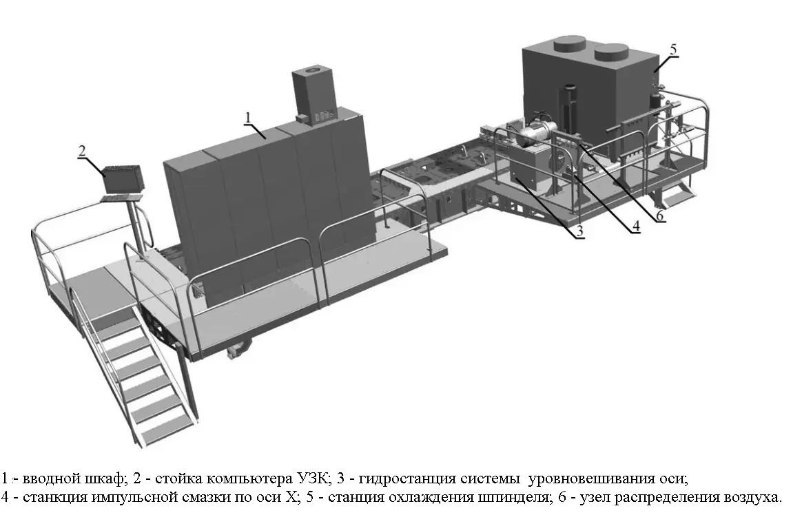
Equipment and maintenance platforms (manual, fig. 31)
Measurement, monitoring and CNC control
The CNC system combines a real-time motion controller with an industrial computer. Operators can use manual and automatic modes, monitor coordinates and drive parameters, view 2D/3D toolpaths and diagnostic information, and access system messages. A wireless pendant supports setup near the workpiece.
- A Renishaw RMP60 touch probe supports part datum setting, dimensional measurement and tool offset correction.
- An optris CTlaser 3MH1 infrared sensor measures process temperature without contact; the manual specifies 150–1,000 °C.
- The axial-force measurement module is installed on a sample-welding stand; its readings are informative and are not used for machine control.
- Emergency-stop buttons are installed around the machine, while travel is limited by end switches.
Machining equipment, controls and auxiliary systems
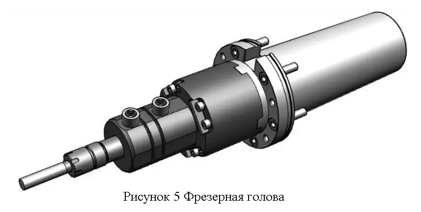
Milling head for machining operations (manual, fig. 5)
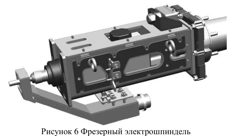
High-speed milling electrospindle (manual, fig. 6)
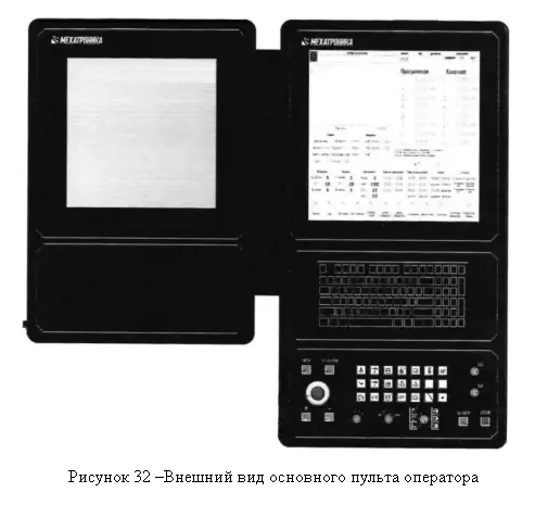
Main CNC operator control panel (manual, fig. 32)
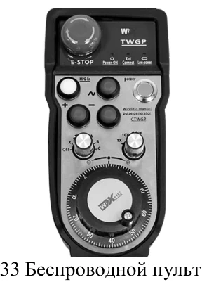
Wireless setup and jogging pendant (manual, fig. 33)
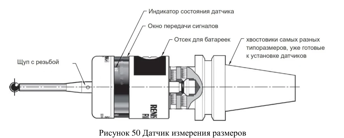
Renishaw RMP60 touch probe (manual, fig. 50)
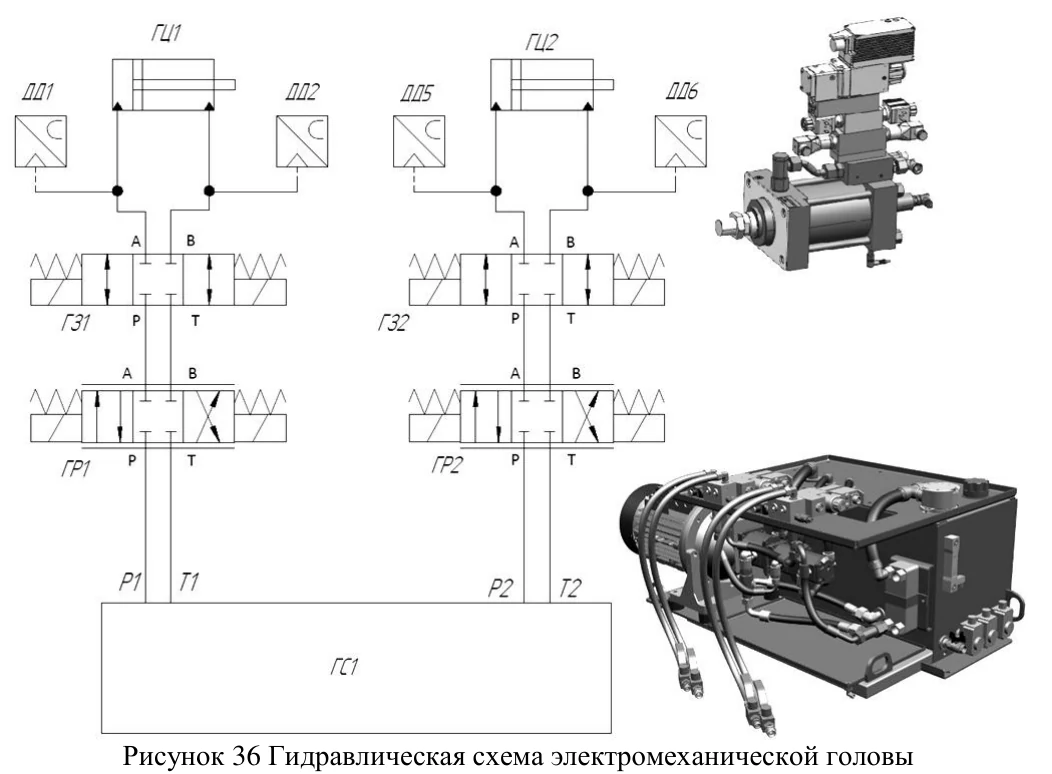
Welding-head hydraulic circuit (manual, fig. 36)
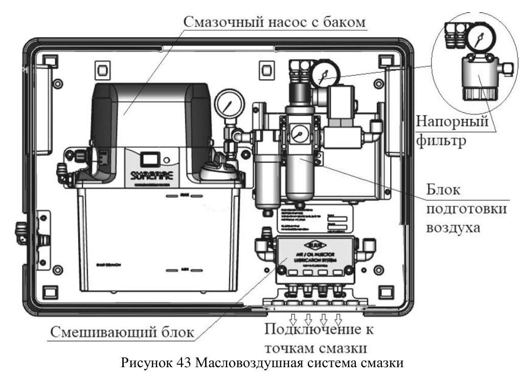
Spindle oil-air lubrication system (manual, fig. 43)
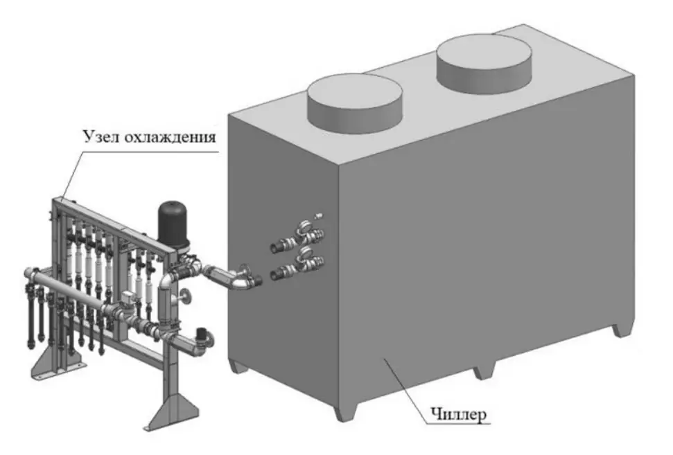
Machine liquid cooling system (manual, fig. 46)
Hydraulics, cooling and pneumatics
- Axis-balancing hydraulic unit210 bar; 15 kW motor
- Spindle hydraulic unit160 bar; 9.2 kW motor
- CoolingWater, 22 kW chiller
- Pneumatic supply45 kW compressor, 10 bar
- Spindle lubricationOil-air lubrication system
- Linear-guide lubricationAutomatic pulse lubrication unit
The hydraulic systems drive spindle feed, pin extension and vertical-axis balancing. Liquid cooling removes heat from the spindle and drives; the pneumatic system provides air barriers, blow-off and auxiliary functions. Service intervals and fluid specifications are defined in the operating documentation.
Operating conditions and installation
- Operating ambient temperature+15 to +35 °C
- Relative humidityno more than 60%
- Electrical supply380 V / 50 Hz, tolerance ±10% / ±5%
- InstallationFoundation, levelling and anchor fastening
Installation and commissioning must follow manual KS0006-00.0000RE and be carried out by trained personnel. The 160-tonne machine requires an engineered foundation and clearances for tank loading, rotation and removal. The manufacturer also specifies limits for vibration, humidity and safety.
Typical production applications
- FSW of aluminium tank and cylindrical structures on a rotary table.
- Manufacture of large aluminium components with sequential access to different weld areas.
- Milling, drilling and boring within the same machine system.
- Process development with adjustable-pin welding and dedicated tool heads.
Process and fixture selection requires drawings, aluminium grade and temper, wall thickness, joint type and location, quality requirements, fixture access areas and target throughput. Workholding and welding parameters are specified for the individual product.
Frequently asked questions
Answers about machine applications, tank dimensions, axes, welding tools and installation conditions.
What products is the Sespel FSW system designed for?
The system performs friction stir welding of aluminium products, including tank and cylindrical structures, and machining of steel and non-ferrous metal workpieces.
What is the workpiece size limit?
Manual KS0006-00.0000RE specifies up to 5,000 mm outside diameter, 2,000 mm height and 3–25 mm thickness. Welding feasibility must be verified for the specific alloy and design.
Can the system weld steel?
The manual specifies FSW for aluminium products. Steel and other non-ferrous metals are listed separately for milling, drilling and boring; steel welding is not confirmed.
How are the machine axes arranged?
The machine has six primary axes X/Y/Z/A/B/U. X/Y/Z provide linear motion, A/B tilt the head and U rotates the table. Separate hydraulic V and W movements control spindle feed and the pin.
What is the rotary table diameter?
The rotary table has a 5,000 mm working surface and a specified speed of 0–1 rpm.
Can the welding pin be adjusted?
Yes. Hydraulic axis W provides 30 mm of pin travel; spindle carriage axis V has a separate 80 mm stroke. Adjustable-pin operation depends on the welding tool.
What are the welding spindle specifications?
The welding spindle drive is rated at 125 kW with a specified speed range of 0–800 rpm.
What machining functions are available?
Milling, drilling and boring are supported. The manual describes a 6 kW milling electrospindle at 6,000–12,000 rpm and dedicated plugging tooling.
Is automatic tool changing supported?
No. The manual describes manual changes of welding and milling tools; the rack is for tool storage.
What measurement equipment is included?
The manual lists a Renishaw RMP60 touch probe and an optris CTlaser 3MH1 non-contact temperature sensor. The sample-stand axial force module is informative and is not used for machine control.
What installation conditions are required?
The machine measures 20,000 × 7,800 × 9,100 mm and weighs 160,000 kg. An engineered foundation, 380 V / 50 Hz power and a +15 to +35 °C working environment are required.
Is there a wireless control and toolpath visualization?
Yes. The manual describes main and auxiliary control panels, a wireless setup pendant, manual and automatic operation, and 2D/3D toolpath visualization.