Error
текст ошибки


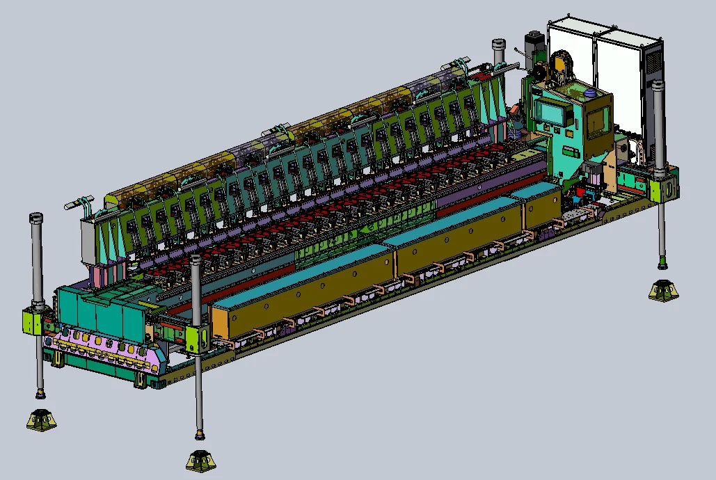
GABARIT-A mobile friction stir welding system
Mobile FSW system for butt and lap welding aluminium semi-finished products 1.5–15 mm thick and up to 8.2 m long. Includes edge preparation, automated clamping and welding parameter monitoring.
About the product
- ApplicationFSW of long aluminium panels
- Workpiece welding thickness1.5–15 mm
- Workpiece welding lengthup to 8 200 mm
- Panel widthup to 3,500 mm with additional supports
- Transport dimensions12 192 × 2 438 × 2 896 mm
- Gross mass39 000 kg
- Power consumption30 kW
- ManufacturerSespel
Contact us for more information about this product.
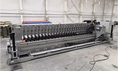 Sespel GABARIT-A FSW system
Error
Description
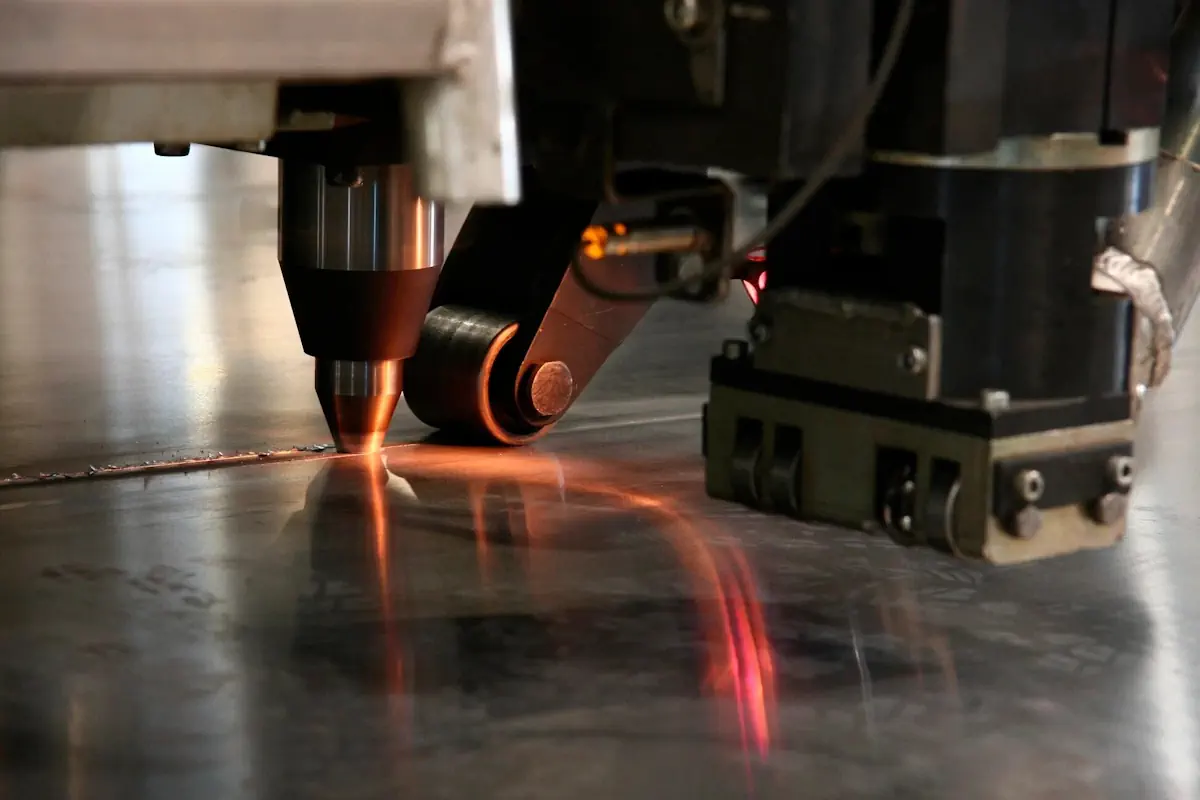
Gabarit-A is a prototype automated friction stir welding (FSW) system developed by Sespel for joining long rolled and extruded aluminium sections. It produces butt and lap joints for lightweight profiled welded panels, including three-dimensional structures up to 100 mm high.
This long cantilever-type machine combines edge preparation, positioning, hydraulic clamping, welding and monitoring with process data recording. Its mobile design allows road or rail transport and deployment at a production site.
Aluminium panel processing capabilities
- Joint typeButt and lap joints
- Workpiece thickness1.5–15 mm
- Input section width80–320 mm
- Input section lengthup to 8 200 mm
- Finished welded panel widthUp to 3,500 mm with additional support devices
- Profiled welded structure heightup to 100 mm
- Welding methodFriction stir welding (FSW)
Panel widths up to 3,500 mm require additional support devices. According to the operating manual, these are not included in the standard system.
System specifications
- System length12 192 mm
- Width in operating position3 122 mm
- Width in transport position2 438 mm
- Height in operating position2 885 mm
- Height in transport position2 896 mm
- Width with hydraulic supports extended3 670 mm
- Gross mass39 000 kg
- Power consumption30 kW
- Climatic versionUHL4 climatic version
- Operating temperaturefrom +1 to +40 °C
Welding and machining tool parameters
- Welding cantilever longitudinal travel speed50–6,000 mm/min
- Tool speed during plunge500–1 500 rpm
- Tool speed during welding200–1 000 rpm
- Welding tool spindle drive power11 kW
- Welding tool Z-axis travel250 mm
- Tool tilt in the XZ plane±3°
- Tool tilt in the YZ plane±1,5°
- Edge machining unit travel speed3–18 m/min
- Milling cutter drive power2.2 kW
- Worktable flatness deviationNo more than 0.2 mm over a length of 8,200 mm
System components
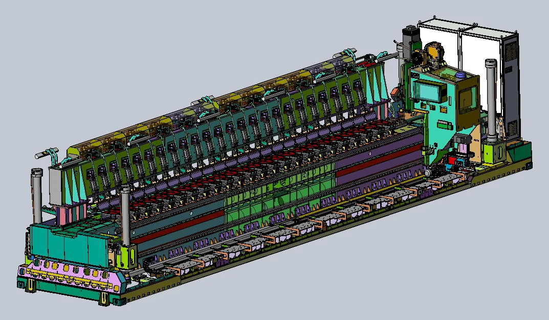
- The bed and worktable carry welding loads and provide a base for precise workpiece positioning.
- Longitudinal and transverse stops position workpieces relative to the weld line.
- Clamps on the bed and load-bearing beam hold workpieces during welding and reduce residual distortion.
- The cantilever, slide and carriage move the welding tool spindle assembly.
- A separate machining unit prepares the workpiece edges before welding.
- The receiving roller conveyor supports the completed welded panel as further sections are joined.
- Main and auxiliary hydraulic and mechanical supports position and stabilise the long structure.
- The automated control system handles edge preparation, clamping, welding, monitoring and process data recording.
System components
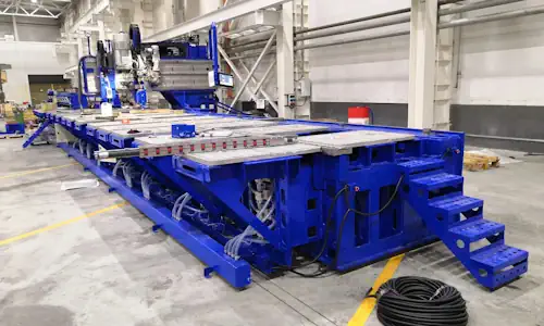
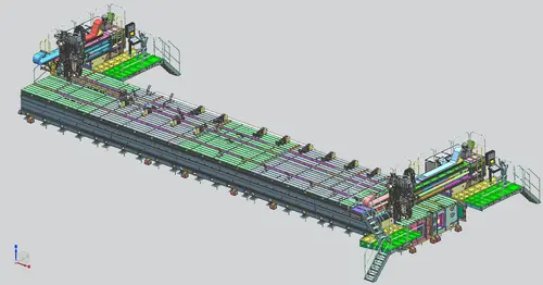
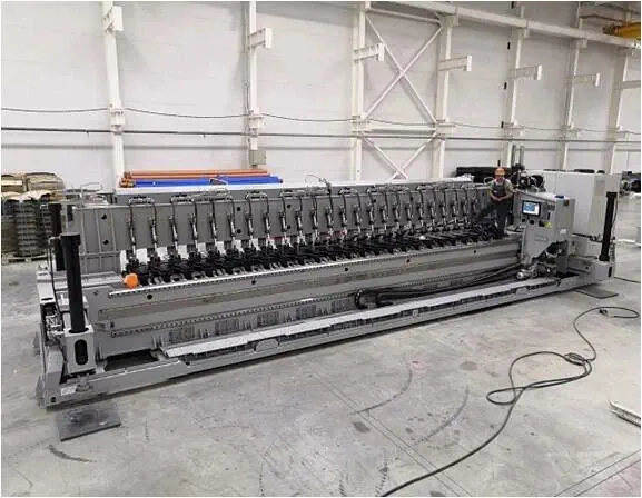
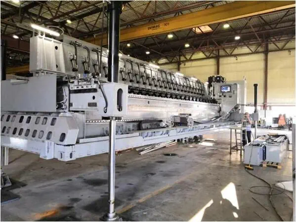
General view of Gabarit-A showing the cantilever, clamps and hydraulic supports
System in operating position with hydraulic supports extended
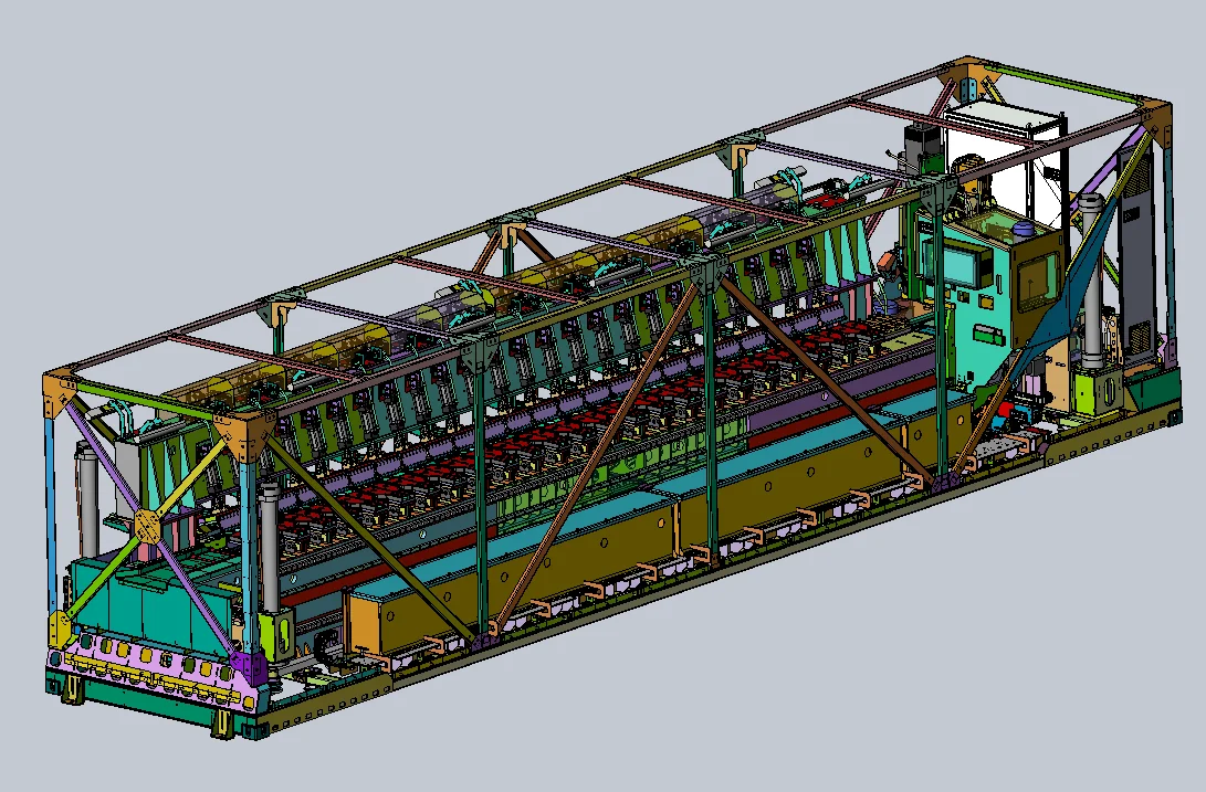
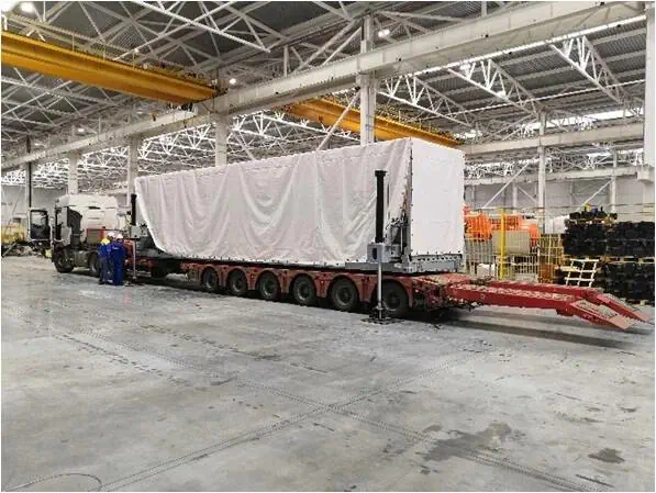
Transport position with protective frame
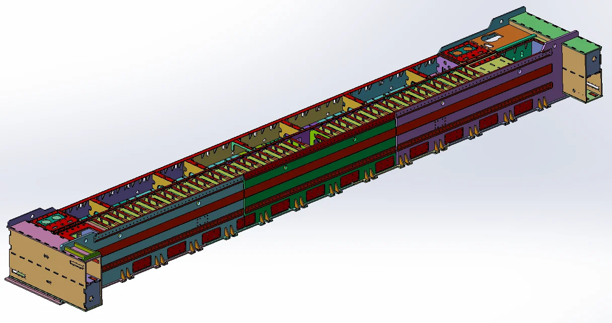
Machine bed with load-bearing structure and guides
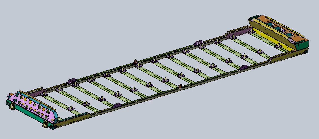
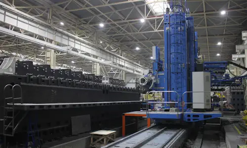
System transport platform
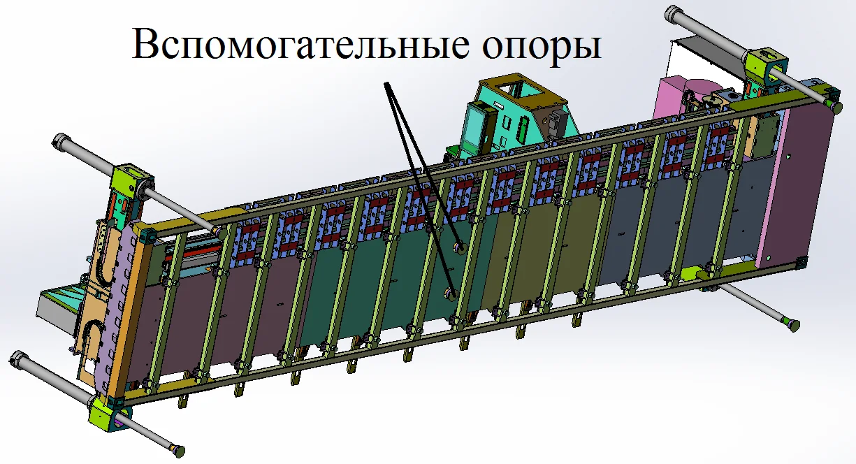
Auxiliary supports for stabilising the base
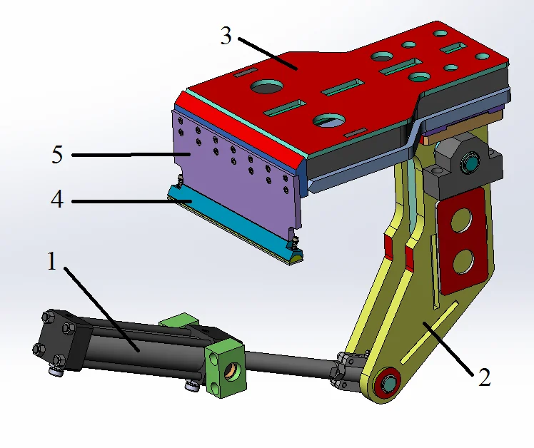
Clamp for securing aluminium workpieces
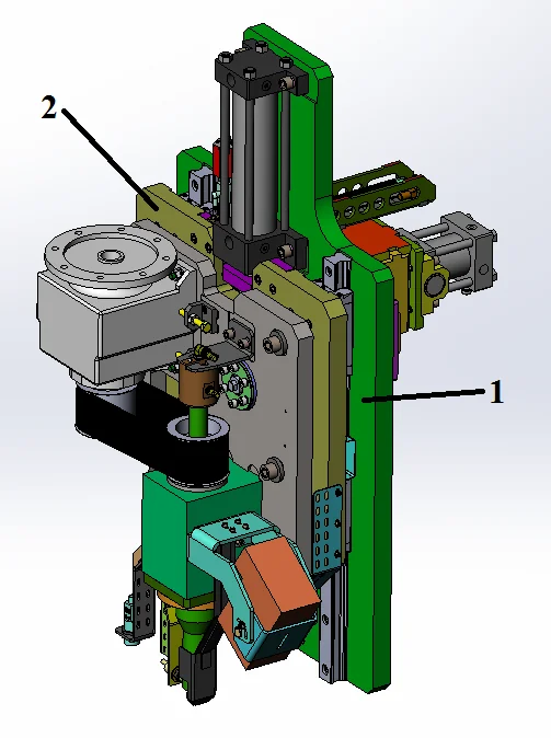
Welding spindle carriage
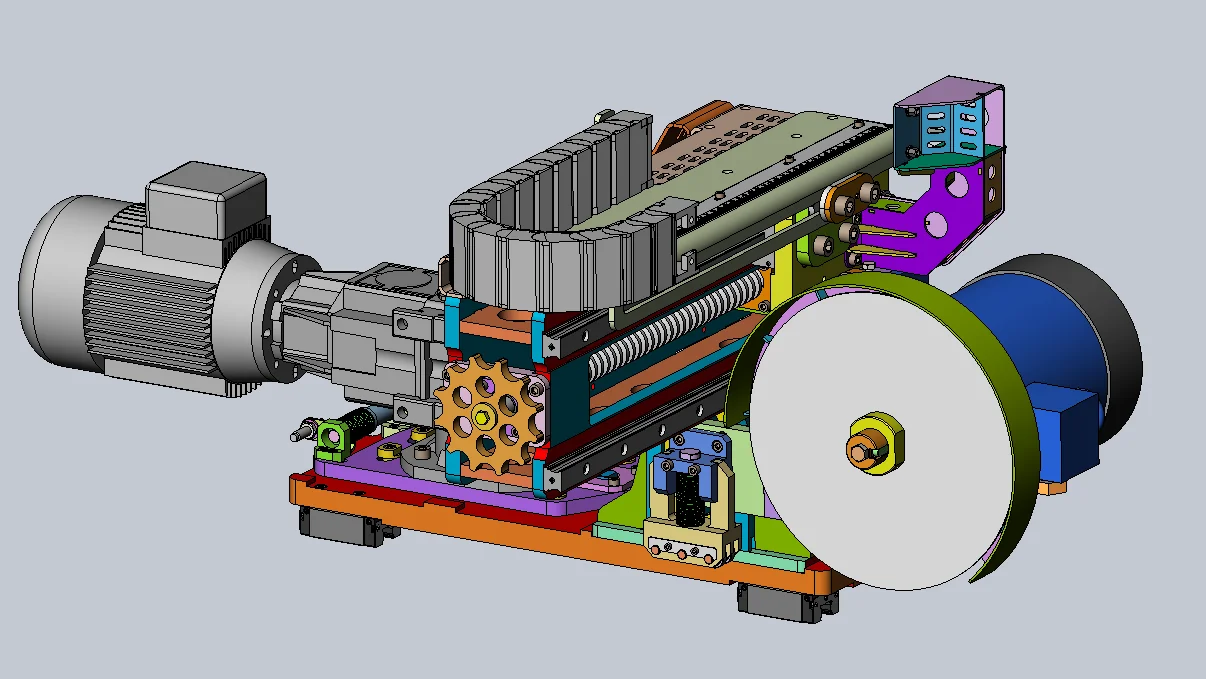
Weld edge preparation unit
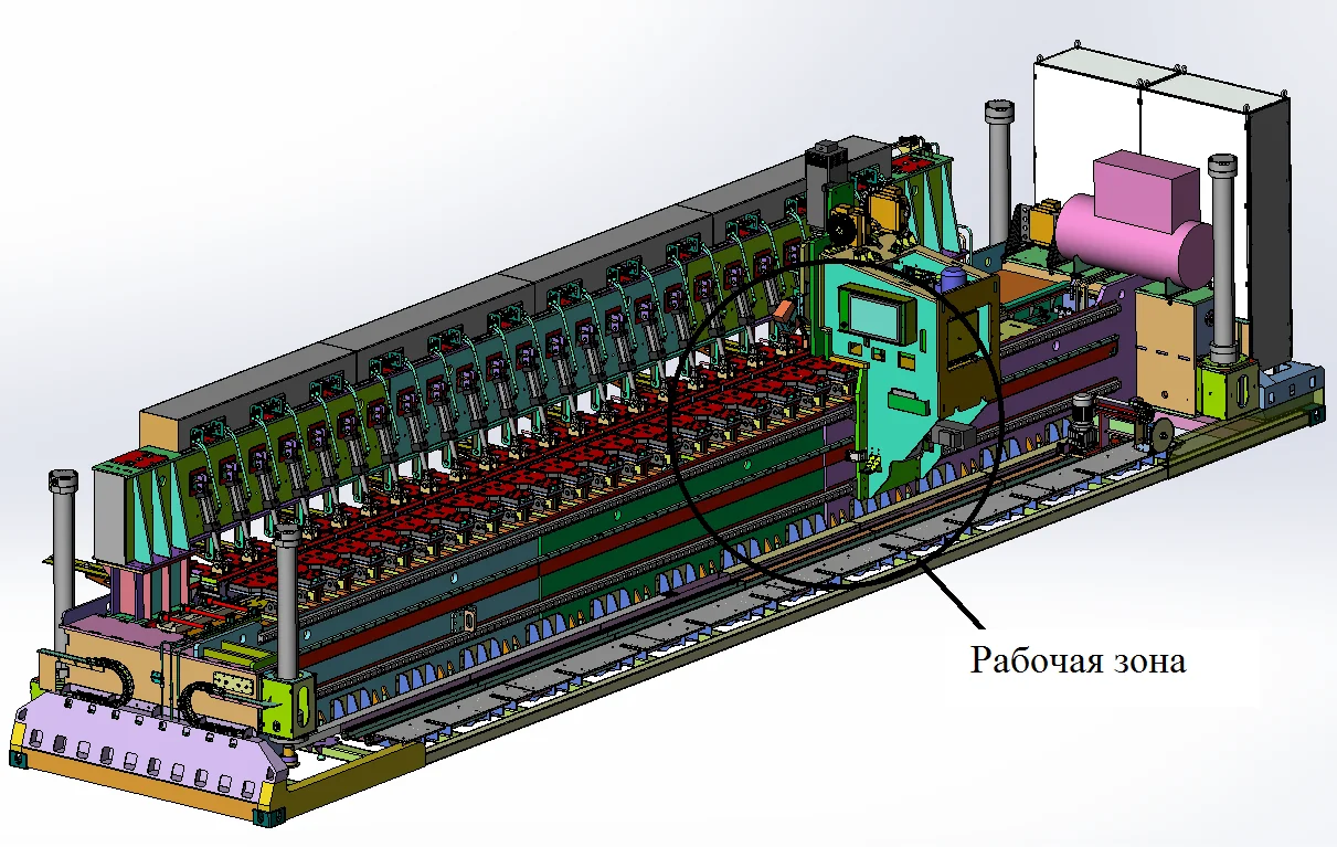
Working area and welding cantilever
Mobile design and on-site installation
The transport configuration uses a platform with container corner fittings. For transport, the machine is stowed and the cantilever, edge machining unit and receiving roller conveyor are secured. At the operating site, it can be unloaded using its own hydraulic supports or external lifting equipment.
After positioning, the machine is levelled using hydraulic supports and an inclinometer, then rests on mechanical supports. This compensates for uneven ground and reduces deflection of the long bed. Installation, foundation and personnel qualification requirements are defined by the operating documentation and the specific site conditions.
Production applications for Gabarit-A
- Welding large, lightweight aluminium panels from rolled or extruded profiles.
- Producing flat and profiled welded panels from aluminium sections.
- Joining panel sections sequentially while supporting the completed portion on a roller conveyor.
- Welding on sites where transporting equipment is more practical than moving a finished large structure.
Information required for selection and implementation
To prepare a proposal, specify the aluminium alloy and temper, section thickness and geometry, required panel length and width, joint types, weld quality and productivity requirements, and availability of additional support tooling. Site conditions, power supply and installation arrangements are agreed separately.
Frequently asked questions
Answers to common questions about design, equipment and project planning.
What aluminium thicknesses can Gabarit-A weld?
The system is designed for rolled and extruded aluminium sections 1.5–15 mm thick. Suitability for a particular alloy and joint is confirmed during process development.
What is the maximum welded panel length and width?
Input sections can be up to 8,200 mm long. Finished welded panels can be up to 3,500 mm wide with additional support devices, which are not included in the system.
What joint types can the system produce?
The system produces butt and lap joints in aluminium sections using friction stir welding (FSW).
Does the system prepare edges before welding?
Yes. It includes a separate edge machining unit. The control system automates workpiece preparation, clamping, welding and process data recording.
Can the equipment be moved to another site?
Yes. The system can be stowed for road or rail transport. It can be unloaded using its own hydraulic supports or external lifting equipment.
What are the transport dimensions?
Length: 12,192 mm; width: 2,438 mm; height: 2,896 mm. Total weight: 39,000 kg. The transport plan must take account of the carrier's requirements and applicable route restrictions.
What are the power consumption and operating temperature?
Power consumption is 30 kW. The operating temperature range is +1°C to +40°C, climatic version UHL4.