Error
текст ошибки


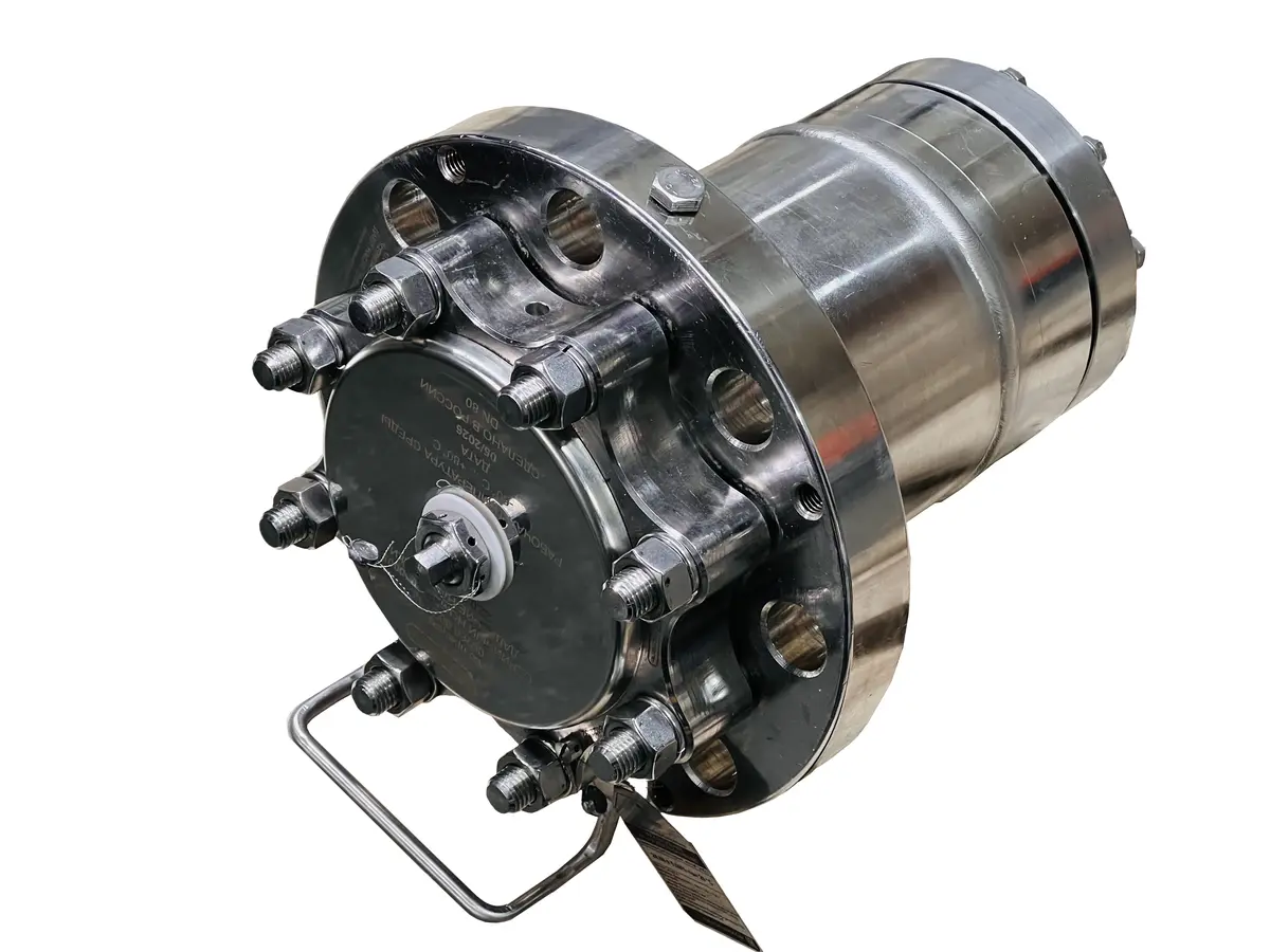
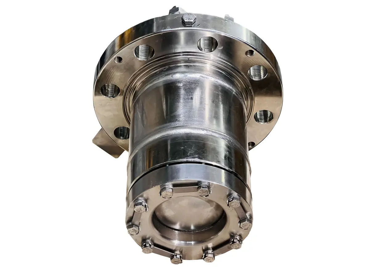
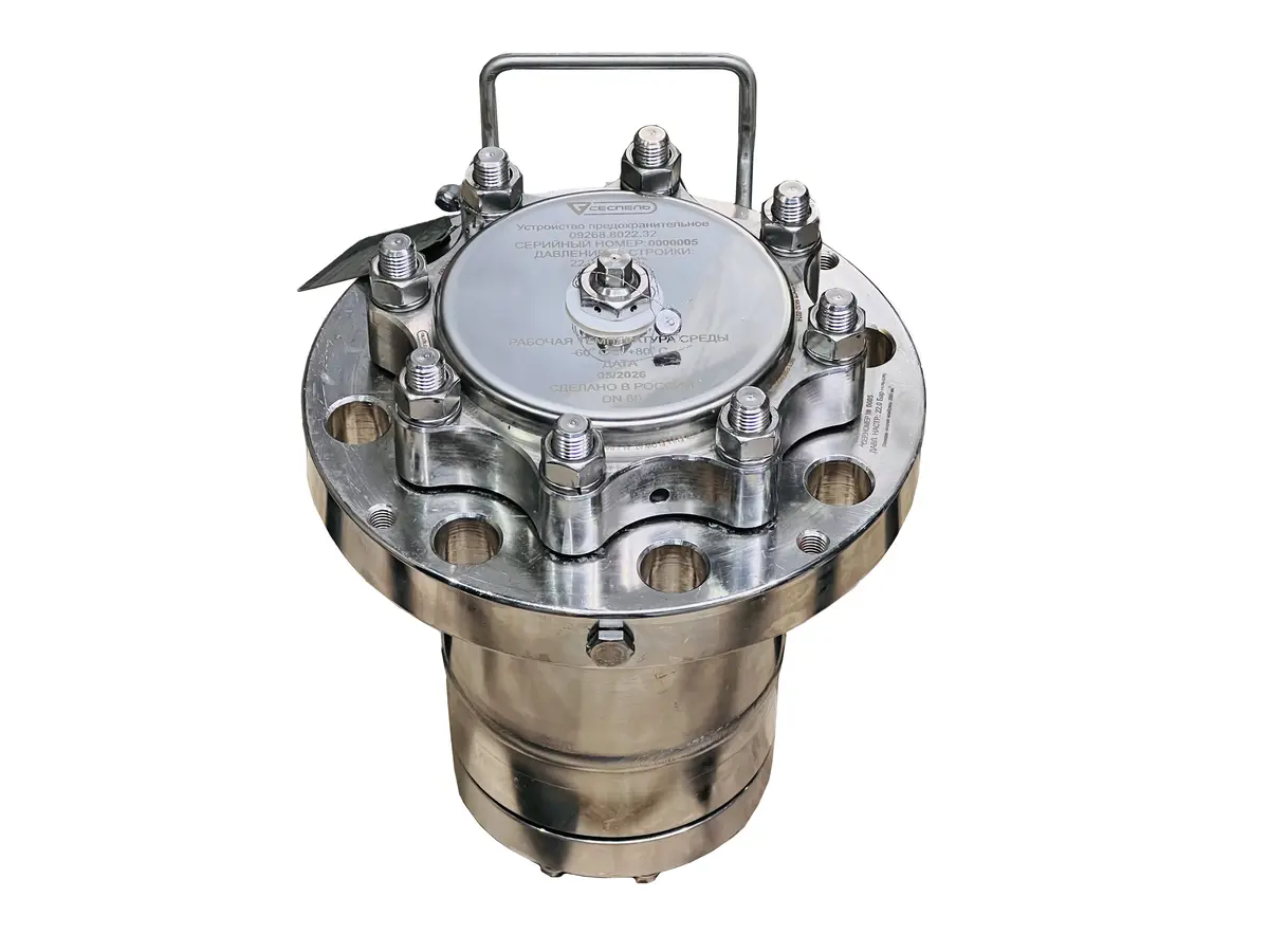
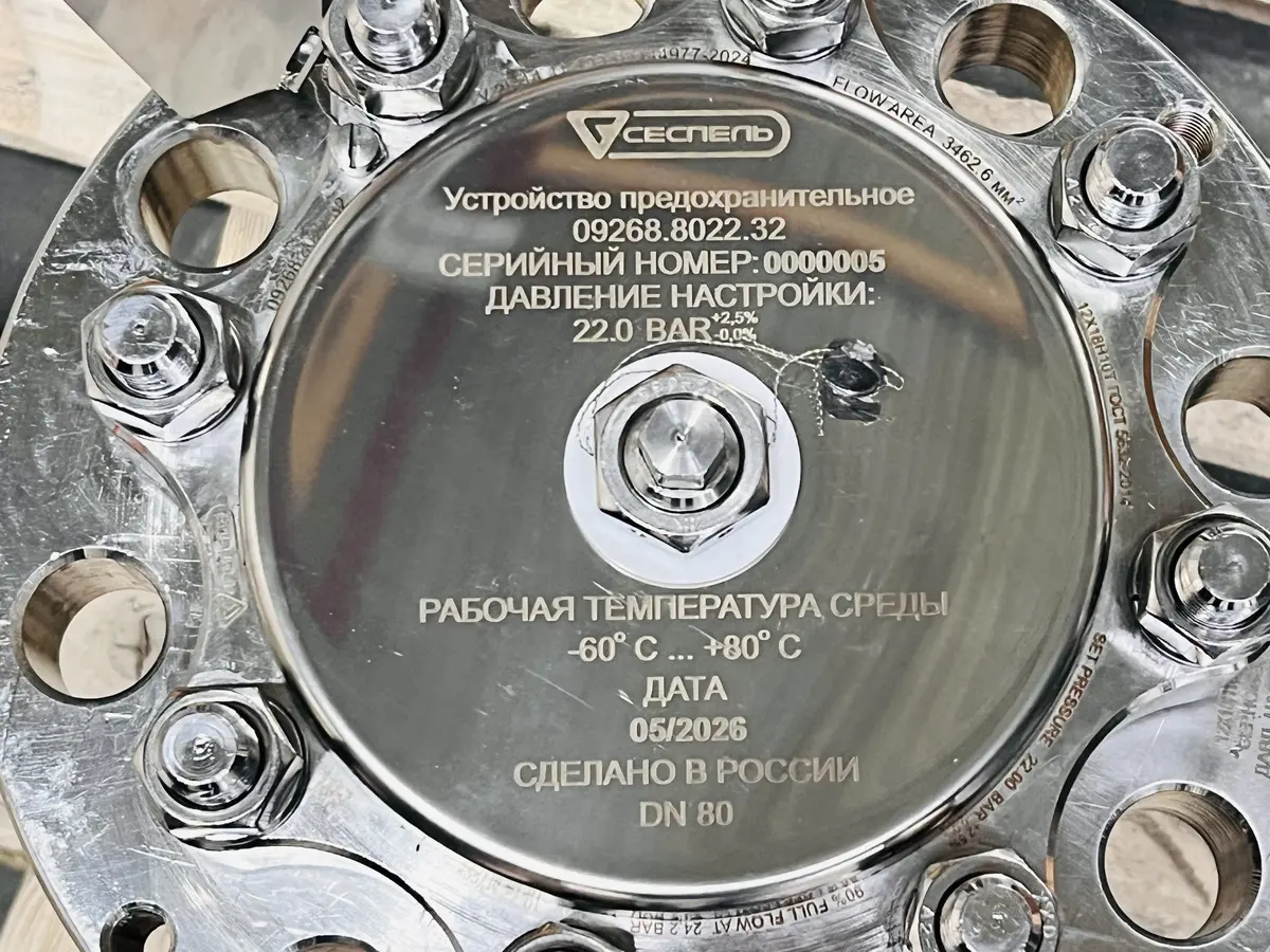
Safety device 09268.8022.32
About the product
- VersionFor tank containers; not for road tankers
- Nominal boreDN 80
- WeightUp to 30.5 kg
- Working mediumAmmonia — tank container version
- Body material12Kh18N10T, GOST 5632-2014
- Disc sealF4PN PTFE, GOST 10007-80
- Nominal pressure PN38.5 bar
- Set pressure22 bar (2.2 MPa)
- Body test pressure57.75 bar (5.775 MPa)
- Working medium temperature−60 to +80 °C
- Climatic versionV1 (−60 to +50 °C)
- Type09268.8022.32
- ManufacturerSespel
Contact us for more information about this product.
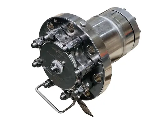 Safety device 09268.8022.32
Error
Description
The 09268.8022.32 safety device combines two protective elements for ammonia tank containers: a rupture disc and a spring-loaded valve set to 22 bar. The disc is upstream of the valve and isolates it from the process medium. During an overpressure event, once the disc ruptures, the medium reaches the valve, which opens the discharge path.
This is a dedicated DN80 flanged version for tank containers, not road tankers. The manual explicitly identifies 09268.8022.32 as the ammonia version. The device operates mechanically, without electrical power or an external command; its purpose is overpressure protection rather than routine process regulation.
Upstream rupture disc: the purpose of isolation
A reverse-domed rupture disc is installed at the base of the device. Clamped between the body and its holder, it forms a barrier between the vessel and the valve assembly. While intact, the disc prevents product from reaching the valve and protects it from exposure to corrosive media. This barrier distinguishes the design from a standalone spring-loaded safety valve.
The rupture disc is a single-use element. After it bursts, the spring-loaded valve can close and stop discharge, but the original isolation from the medium is not restored. Returning the device to service requires disc replacement and the checks specified in the manual. Replacement disc parameters must be verified against the documentation for the individual unit; the valve setting alone is not a substitute for disc selection data.
Monitoring the space between the disc and valve
The pressure gauge is connected to the space between the rupture disc and the safety valve. It is used to monitor disc integrity and activation. It monitors a separate cavity within the device: readings must be interpreted in accordance with the connection arrangement, rather than automatically treated as the pressure throughout the tank container.
The design includes a unit protecting the gauge against vacuum pressure caused by temperature changes. It consists of a ball, spring and bush; the manual describes the opening of the passage it seals when the disc ruptures. A support protects the gauge from mechanical damage. These elements support monitoring of the rupture-disc assembly without an external actuator.
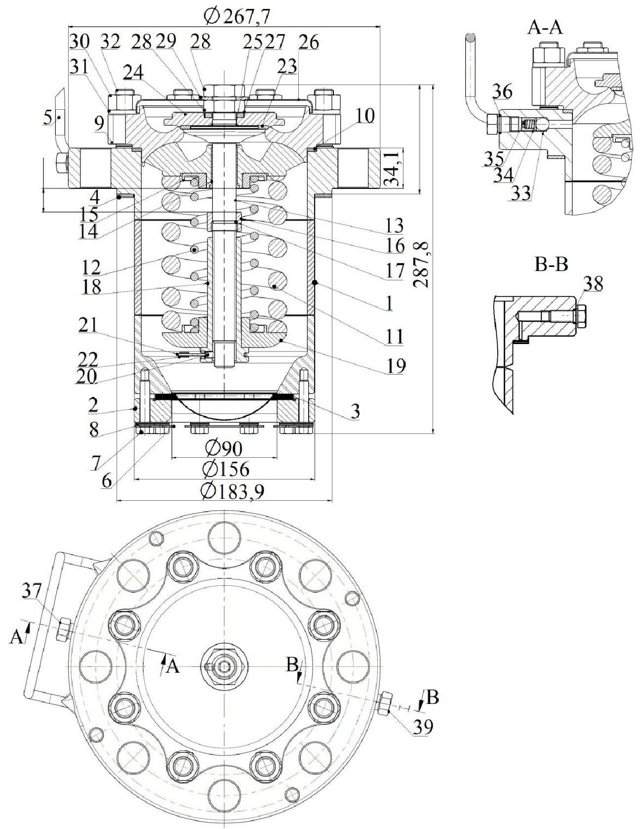
09268 cross-section: rupture disc, spring-loaded valve and gauge unit — Figure 1 from the operating manual
Discharge and reclosing
After the disc ruptures, medium pressure acts on the valve disc through the inlet passage. The large and small springs hold it against its seat until the pressure force exceeds their closing force. The disc then lifts to open the outlet passage. The manual describes proportional action: lift depends on how far pressure exceeds the threshold. As pressure falls, the springs return the disc to its seat.
Closing force is set by an adjusting nut, locked with a screw and secured by a sealing cable and clamp. The stem moves within an F4PN PTFE guide bush, and a gasket on the stem seals the valve disc. A protective cap at the top prevents water from collecting on the outlet side and impairing operation if it freezes.
09268.8022.32 specifications
- Working mediumAmmonia — tank container version
- Set pressure22 bar (2.2 MPa)
- Nominal boreDN 80
- Nominal pressure PN38.5 bar
- Body test pressure57.75 bar (5.775 MPa)
- Working medium temperature−60 to +80 °C
- WeightUp to 30.5 kg
The body is made of 12Kh18N10T stainless steel and the disc seal of F4PN PTFE. The materials table specifies AISI 302 steel for the springs. Seat tightness is Class A to GOST 9544-2015. Climatic version V1 refers to ambient air from −60 to +50 °C and must not be confused with the medium temperature range.
The 22 bar setting, PN 38.5 bar nominal pressure and 57.75 bar test pressure serve different purposes. The latter two are not activation pressures. Unlike 09268, the 09267 LPG tank container version on this site is set to 18 bar and has no rupture-disc assembly. A shared DN80 bore does not make these products interchangeable.
Installation with access to both assemblies
Install the device vertically with the outlet facing upwards on a level flange surface without misalignment. Leave space around it to inspect and service every part. Before installation, check completeness, documentation, seals and freedom from damage, and remove preservative grease and contamination. Remove transport plugs immediately before installation.
Valve maintenance and seal replacement
The manual specifies inspection at installation and at least every three months, annual functional checks, and replacement of all sealing elements every five years. Inspections cover damage, tightness and seal integrity. These scheduled tasks do not replace the requirement to change the rupture disc after activation.
The design allows the disc seal to be replaced in place without removing the valve, but only with no pressure in the system and in accordance with the manual. Figure 2 shows the gasket on the stem and its retaining parts. Repairs must be performed by an authorised organisation using original spare parts. The manual specifies a service life of 10 years and a rated life of 6,000 cycles; this repeat-operation rating does not apply to the single-use rupture disc.
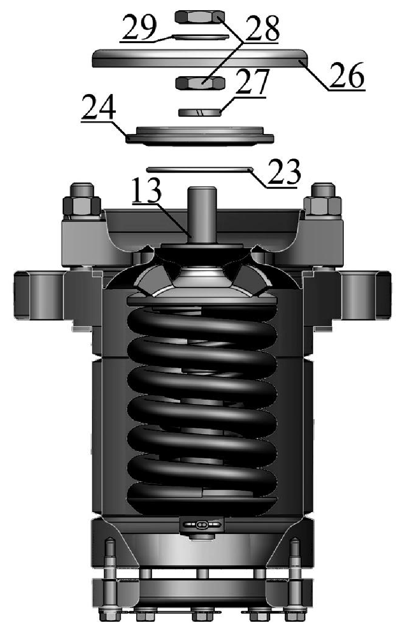
Valve disc gasket and retaining parts — Figure 2 from the 09268 operating manual
Operating manual
| 09.268-0000РЭ | 09268 safety device operating manual | Open | Unknown |
Certificates
| 26.44.01.00649.130 | Type Approval Certificate | Open | Unknown |
Frequently asked questions
Answers to questions about selecting, connecting and operating the product.
Which media is the 09268.8022.32 designed for?
The version shown is intended for ammonia tank containers, with a 22 bar set pressure and a bursting disc. The 09267 valve set to 18 bar is intended for LPG tank containers.
Why is a bursting disc installed upstream of the valve?
It isolates the valve from the working medium until activation. After the disc bursts, the spring-loaded valve relieves pressure. A gauge monitors pressure between the disc and the valve.
Does the device need an electrical power supply?
No. The valve and disc respond mechanically to pressure. The device requires no external control or electrical power source.
Can operation continue after the disc has burst?
The bursting disc is single-use and must be replaced after activation. The checks and maintenance required by the manual must be completed before returning the equipment to service; valve closure alone is not sufficient.
How does set pressure differ from PN and test pressure?
This version has a set pressure of 22 bar. PN 38.5 bar is the nominal pressure rating, while 57.75 bar is the body test pressure. These values must not be substituted for the set pressure.